Full PDF - ClareOne Wireless Security and Smart Home Panel User Manual (DOC ID 1871)
Contents
Important information
Limitation of liability
Introduction
Packages contents
Specifications
Installing the panel
ClareOne Panel menus
ClareOne menu bar
ClareOne status bar
ClareOne quick settings menu
Security
Security user management
Operating security
Settings
Display
User Settings
Installer Settings
About
User and Installer Settings
User Management
WiFi
Time Zone
Security & Arming
Sensor Management
Restart
System Test
Check for Updates
Panel Reset
Demo Mode
Basic operation
Panel states
Panel LED
Maintenance
Contact
Appendices
Quick reference
Trouble conditions
Panel zone list tracking
Sensor installations and specifications
Important information
Limitation of liability
To the maximum extent permitted by applicable law, in no event will Clare Controls, LLC. be liable for any lost profits or business opportunities, loss of use, business interruption, loss of data, or any other indirect, special, incidental, or consequential damages under any theory of liability, whether based in contract, tort, negligence, product liability, or otherwise. Because some jurisdictions do not allow the exclusion or limitation of liability for consequential or incidental damages the preceding limitation may not apply to you. In any event the total liability of Clare Controls, LLC. shall not exceed the purchase price of the product. The foregoing limitation will apply to the maximum extent permitted by applicable law, regardless of whether Clare Controls, LLC. has been advised of the possibility of such damages and regardless of whether any remedy fails of its essential purpose.
Installation in accordance with this manual, applicable codes, and the instructions of the authority having jurisdiction is mandatory.
While every precaution has been taken during the preparation of this manual to ensure the accuracy of its contents, Clare Controls, LLC. assumes no responsibility for errors or omissions.
Full PDF - ClareOne User Manual (DOC ID 1871)
Introduction
The ClareOne Wireless Security and Smart Home Panel (CLR-C1-PNL1) is a smart home hub featuring customizable home automation and security control. The ClareOne eliminates the need for separate control and customization devices.
Package contents
Note: Ensure all accessories are included. If not, contact the dealer.
- 1 x ClareOne panel (CLR-C1-PNL1)
- 1 x Battery (CLR-C1-BATT, located inside battery compartment of the panel)
- 1 x Wall mount bracket and Kickstand (CLR-C1-STND)
- 1 x Power supply (CLR-C1-12V)
- 1 x USB-C Ethernet adapter (CLR-C1-ETH)
- 1 x ClareOne Quick Start Guide (DOC ID 1885)
- Mounting hardware (screws and wall anchors)
- 1 x ClareOne bezel – white (CLR-C1-BZL-W)
- 1 x ClareOne bezel – black (CLR-C1-BZL-B, attached to panel)
Compatible sensors and accessories:
- ClareOne Mini Door/Window Sensor, white (CLR-C1-MDW-W)
- ClareOne Mini Door/Window Sensor, brown (CLR-C1-MDW-B)
- ClareOne Keyfob (CLR-C1-KF)
- ClareOne PIR Motion Sensor (CLR-C1-PIR)
- ClareOne Carbon Monoxide Detector (CLR-C1-CO)
- ClareOne Smoke Detector (CLR-C1-SMK)
- ClareOne Panic Pendant (CLR-C1-PNC)
- ClareOne Water Detector (CLR-C1-WTR)
- ClareOne Door Window Sensor with External Contact (CLR-C1-DWCNT)
- ClareOne Door Window Sensor with Shock Sensor (CLR-C1-DWSHK)
- ClareOne Rate of Rise Heat Detector (CLR-C1-HT)
- ClareOne 16-Zone Wired Input Module (CLR-C1-WD16)
- ClareOne Wireless to Wireless Takeover Module/Repeater (CLR-C1-W2WL)
- ClareOne Glass Break Detector (CLR-C1-GB)
- ClareOne Outdoor Door Window (CLR-C1-ODDW)
- ClareOne Z-Wave Siren (CLR-C1-ZW-SRN)
Specifications
|
Touchscreen |
|
|
Size |
7 in (18 cm) |
|
Resolution |
1024 × 600 |
|
User Interface |
|
|
Status LED |
Multi-color |
|
Voice announcement |
System state, sensor state, disarm state |
|
User codes |
Up to 99 users and 10,000 possible codes |
|
Proximity sensor |
5 ft (1.52 m) auto-wake up motion detection |
|
Radio/Network |
|
|
WiFi |
WiFi 802.11 a/b/g/n/ac dual band 2.4/5G |
|
Ethernet/LAN |
USB-C to ethernet adapter |
|
Z-Wave |
Z-Wave Plus |
|
Cellular |
Verizon LTE with two-way voice |
|
Security R/F |
Encrypted, two-way, 433MHz, 1 partition, 128 sensor zones |
|
Siren and Audio |
|
|
Internal |
Piezo, above 87db at 10 ft (3.04 m) |
|
Contact closure port |
1 |
|
Wireless |
Z-Wave |
|
Audio detection |
T3 and T4 alarm detection (smoke and CO) |
|
Power/Battery |
|
|
DC Power |
12VDC 2500mA, Input 100-240VAC 50/60Hz |
|
Connector |
Micro USB or screw terminals |
|
Power consumption |
30W maximum |
|
Battery type |
Rechargeable lithium-ion battery, 5200mAh |
|
Maximum battery voltage |
4.35V |
|
Battery duration |
24 hours + 4 minutes of continued alarm after the 24-hour period |
|
Changeable battery |
Yes, user can change |
|
Mechanical |
|
|
Tamper switch |
Panel tamper switch with spring release and status reporting |
|
Operational temperature |
32 to 120° F (0 to 48.8° C) |
|
Humidity |
85 ± 5% at 86 ± 3°F for 24 hours |
|
Mount |
Includes wall and two position tabletop stand |
|
Panel dimensions |
7.7 × 5.3 × .8 in. (194.8 × 134.9 × 20.6 mm) |
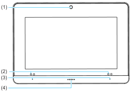
Figure 1: ClareOne Panel - front
|
(1) Camera |
|
(3) Microphones (on each side) |
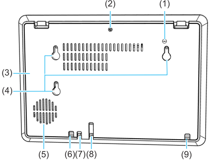
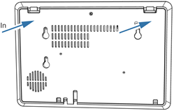
Figure 2: ClareOne Panel - exterior rear
|
(1) Tamper button |
|
(6) DC routing hole #1 |
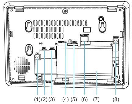
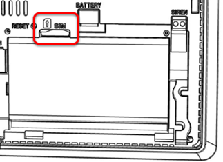
Figure 3: ClareOne Panel - interior rear
|
(1) DC wiring terminal |
|
(5) SIM card slot |
Full PDF - ClareOne Wireless Security and Smart Home Panel User Manual (DOC ID 1871)
Installing the panel
Only qualified installation technicians should install the panel. Clare Controls does not assume responsibility for damages caused by improper installation, connection to the network, or use of the device.
Installation options
The ClareOne panel can be installed using a desktop stand or a wall mount.
Power options
The panel can be powered by the provided power supply with a micro USB cable, using the provided power supply with Cat5/6 cable, or using the provided power supply with 22AWG or thicker shielded security wiring. For details on the ClareOne panel power options, see Power supply options.
Note: In the case of a power outage, the battery in the panel lasts 24 hours plus an additional 4 minutes of alarm signaling.
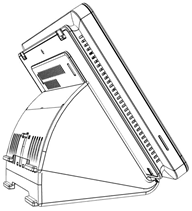
Installation option 1: Desktop
Option 1 uses the included kickstand.
To desktop mount the panel:
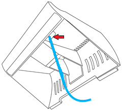
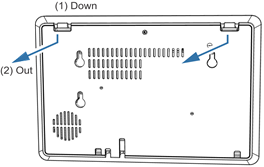
- Remove the panel’s back plate by pressing down on the 2 tabs and pulling the back plate outward, exposing the battery.

- Route the power supply cable through the hole in the bottom right side of the kickstand.
- Verify that the battery is plugged in, and then attach the power supply to the panel.
Note: For other power options, see Power supply options.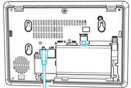
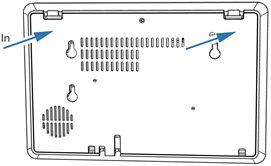
- Attach the panel’s back cover, gently pressing it into place. Verify that the tabs are both fully pressed in.
- Press the sides of the back plate against the back of the panel, making sure there is no gap between the back plate and the panel.
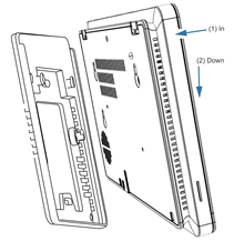
- Align the mounting holes in the back of the panel with the stubs on the kickstand, and then press kickstand to the rear of the panel.
- Slide the panel down, locking it into place.
- Plug the opposite end of the power supply into an electrical outlet.
The panel automatically powers up.
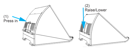
Note: Do not connect to a receptacle controlled by a switch. - (Optional) The viewing angle of the panel can be adjusted by pressing the kickstand tab and sliding the base up or down to the desired position, locking it into place.
Installation option 2: Wall mounted
Option 2 uses the included wall mount bracket. The recommended height for mounting the panel is 48 in. +/- 12 in. based on the comfort level of the end user.
To wall mount the panel:
- Select a location for the panel that is close to an outlet, and then run a connection from the 12VDC supply to the selected installation location.
- Place the mounting bracket against the selected wall location or gang box, ensuring that the power cable goes through the center of the mounting bracket.
Note: The cable does not need to go through the mounting bracket if the power cable does not run through the wall. - Using included screws securely attach the bracket to the gang box or wall. See the methods below.
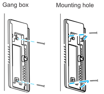
a. Gang box: Using 2 of the included machine screws, secure the bracket to the existing gang box.
b. Mounting hole: Mark the locations of the 4 holes in the wall mount bracket on the wall, be sure to keep the bracket level when marking the locations. Using a power drill with 5 mm bit, drill a hole at each location. Insert one of the included wall anchors into each of the 4 holes. Match the wall mount bracket to the anchor locations. Secure the panel to the wall using the provided screws in the 4 holes. - Remove the panel’s back plate by pressing down on the 2 tabs and pulling the back plate outward.
- Verify that the battery is plugged in, and then attach the power supply to the panel.

- Attach the panel’s back cover, gently pressing it into place.
- Press the sides of the back plate against the back of the panel, making sure there is no gap between the back plate and the panel.
- Press the panel onto the mounting bracket, and then slide the panel down until it locks into place.
- Plug the opposite end of the power supply into an electrical outlet.
The panel automatically powers up.
Note: Do not connect to a receptacle controlled by a switch.
Power supply options
The ClareOne Panel has 2 power options: localized (using provided power supply with micro USB within 6 ft of the installation location) and remote (using CAT5/6 or 22AWG or thicker shielded security wire to extend the reach up to
100 ft from the installation location).
Localized power
The power supply provided with panel come with a 6 ft micro USB cable attached.
Note: Only use the provided 12VDC power supply. Do not use any other power supply with the panel.
To use localized power:
- Remove the panel’s back plate by pressing down on the 2 tabs and pulling the back plate outward.
- Plug the micro USB cable into the panel’s micro USB DC port. See Figure 3: ClareOne Panel - interior rear on page 4.
- Replace the back plate, and then plug the power supply into the closest wall outlet.
Note: Do not connect to a receptacle controlled by a switch.
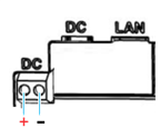
Remote power
For installation locations that are further than 6 ft from the nearest outlet, the power supply cable can be removed and replaced with a CAT5/6 cable or an 22AWG or thicker shielded security wire. This allows the power supply to be located up to 100 ft away from the panel. For details regarding wire gauges and distance, see ClareOne Remote Power Tech Bulletin (DOC ID 1937).
Note: When using CAT5/6 cable the single wires must have a minimum gauge of 24AWG. In addition, a twisted pair of the wires must be used to connect to each of the positive and negative terminals in order to reach 100 ft.
To power a panel more than 6 ft away from an outlet:
- Remove the panel’s back plate by pressing down on the 2 tabs and pulling the back plate outward, exposing the rear interior.
- Carefully insert the positive end of the wire into the positive terminal of the DC power terminal.
- Carefully insert the negative end of the wire into the negative terminal of the DC power terminal.
- Replace the back plate on the panel.
- Connect the wires to the positive and negative terminals on the power supply.
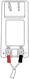
- Secure the power supply mounting bracket to the closest wall outlet using the provided screws, and then plug the power supply into the outlet.
Note: Do not connect to a receptacle controlled by a switch. - Use the provided zip tie to loop through the mounting bracket, securing the power supply.
Panel battery specifications and maintenance
The ClareOne Panel uses a rechargeable lithium-ion battery, specs listed below.
Table 1: ClareOne Panel Battery Specifications
|
Battery type |
Rechargeable Lithium-ion battery, 5200mAh |
|
Maximum battery voltage |
4.35V DC |
|
Maximum charging current |
2600mA |
|
Charging time |
6.5 hours (at standard charge rate of 1040mA) |
|
Manufacturer |
Guangdong Pow-Tech New Power Co., Ltd. |
|
Manufacturer part number |
PT985082-PCM5200 |
|
Connector |
3 pin latching connector |
|
Battery duration |
24 hours + 4 minutes of continued alarm after the |
|
Changeable battery |
Yes, user can change |
Battery maintenance
The battery is rated to last over 18 years in typical installation environments. For proper upkeep and panel reliability, the rechargeable battery should be periodically tested by verifying that the panel operates without AC power. If the battery needs to be replaced, a replacement battery can be ordered using Clare Controls part number CLR-C1-BATT. The current battery capacity is displayed by the battery indicator in the Status Bar (Figure 9).
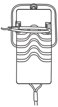
To replace the battery:
- Remove the panel’s back plate
- Press down on the battery cable header tab, and then carefully pull down on the header, releasing it from the connector on the panel.
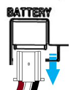
- Remove the battery and dispose of it properly.
- Insert the new battery’s header into the battery port on the panel.
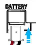
- Gently place the battery into position with the battery’s cabling going above the battery in the back of the panel.
- Return the panel’s back plate.
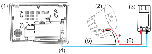
Wired siren
The ClareOne Panel has a 2 pin terminal connector to attach an external wired siren. The connector is labeled as “SIREN” and uses a 2-screw terminal. The siren output acts as a simple contact closure, resulting in the wiring polarity being irrelevant for connection. The wired siren and its power supply should be connected as shown below. Use Class B wiring for all connections.
For more information on ClareOne Panel wired sirens, see ClareOne Wired Sirens Integration Notes (DOC ID 1936).
Figure 4: Wired siren connection
|
(1) ClareOne Panel |
|
(4) Negative wire |
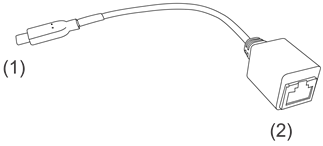
Wired Ethernet
The ClareOne Panel defaults to using WiFi for home network connection. However, a wired Ethernet connection is possible using the included USB-C Ethernet adapter. Connect the USB-C Ethernet adapter into the USB-C port on the interior back of the panel, and then connect a Cat5/6 Ethernet cable to the other end of the adapter.
Figure 5: USB-C Ethernet adapter
|
(1) USB-C plug connector |
|
|
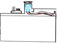
SIM card slot
The ClareOne Panel comes with a factory installed SIM card. The provided SIM card is designed for use with the ClareOne panel.
Note: Do not use a non-Clare Controls SIM card. If a non-Clare Controls SIM card is used, the panel will not report correctly. Using a non-Clare Controls SIM card may result in a security risk.
Figure 6: ClareOne Panel SIM card slot
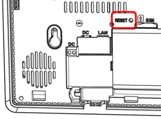
RESET button
A recessed button is located under the panel’s back plate and can be used to power cycle the panel. A paperclip or other small probe is needed to press the button.
Figure 7: ClareOne Panel RESET button
Full PDF - ClareOne Wireless Security and Smart Home Panel User Manual (DOC ID 1871)
ClareOne setup wizard
The ClareOne panel has the ClareHome app pre-installed. Follow the setup wizard to connect to the home’s WiFi and add sensors.
To setup the panel:
- Tap the screen.
The Set Up Wizard displays.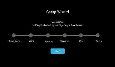
- Tap Start.
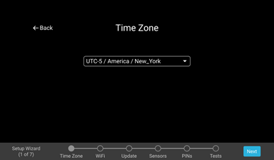
- Select your time zone from the drop-down, and then tap
Notes- ClareHome uses the location of the device for timers and events.
- Tap <- Back to return to the previous step/screen.
- Scroll and tap to select the desired network, enter the password, and then tap Ok.
Note: Tap to hide the keyboard.
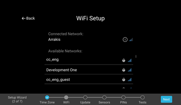
- Tap Next, and then the panel auto searches for available updates.
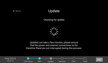
Note: This may take some time. If there are available updates, the panel reboots.
Once the panel updates, or if there are no available updates, the Success screen displays.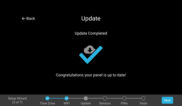
- Tap Next, and then add the desired sensors.
For full sensor configuration and management, see Sensor Management.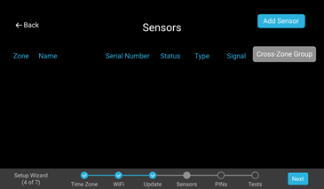
- Tap Next to continue in the wizard, and then configure the Installer and Master PINs.
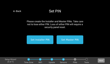
Notes- The Installer PIN must be 5 digits and the Master PIN must be 4 digits.
- If the Master/Installer PINs are lost, the user cannot access Master/Installer menus or features. Do not forget these codes.
a. Tap Set Installer PIN, and then enter the desired 5-digit PIN.
b. Verify the PIN, and then tap Next.
You are returned to the Set PIN page.
c. Tap Set Master PIN, and then enter the desired 4-digit PIN.
d. Verify the PIN, and then tap Next.
You are returned to the Set PIN page.
- Tap Next to continue the wizard.
- Run any desired diagnostic tests, and then tap Done.
Note: Once installation is complete test the panel and sensors. See System Test.
The Setup Complete page displays.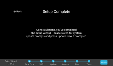
- Tap Finish.
Full PDF - ClareOne Wireless Security and Smart Home Panel User Manual (DOC ID 1871)
ClareOne Panel menus
Use the following information to understand and navigate the ClareOne panel.
ClareOne menu bar
The ClareOne panel menu bar options run along the bottom of the screen and features 4 icons with an Emergency button. This menu is available on any screen in the panel, allowing easy access for the panel’s features.
Figure 8: Menu bar

Table 2: ClareOne menu bar
|
Icon |
Name |
Description |
 |
Security |
The Security page allows the user to access and control their security system. |
 |
Favorites |
The Favorites page allows the user to customize a page with all of their most used devices and scenes. |
 |
Activity |
The Activity page allows the user to see a list of security events for their security panel. For example, when the panel was armed. |
 |
Settings |
The Settings page allows a user access to panel settings and customizations. User and Installer settings are accessed through the Settings page. |
 |
Emergency |
The Emergency page allows users easy access to contact their monitored central station. |
ClareOne status bar
The status bar displays the panel’s current volume, cellular connection, WiFi, battery level, and time.
Figure 9: Status bar
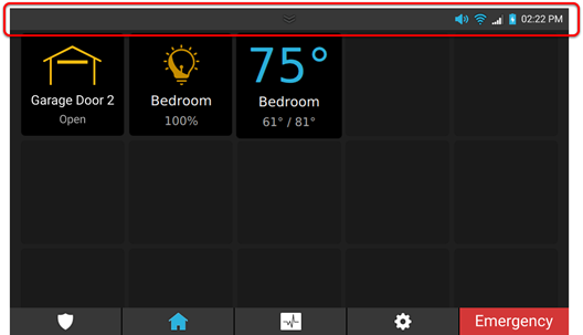
Table 3: ClareOne status bar
|
Icon |
Name |
Description |
|
|
Quick settings |
This icon allows for the user to access the ClareOne's quick settings menu. |
|
|
Volume |
The volume icon indicates if the panel’s volume is on/off. |
 |
WiFi |
The WiFi icon indicates the panel’s current WiFi strength. |
 |
Cellular |
The cellular icon indicates the panel’s current cellular status. |
 |
Battery |
The battery icon indicates the panel’s current battery level. |

 /
/
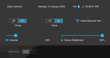
ClareOne quick settings menu
The ClareOne quick settings menu allows the user access more detailed information on the date, battery percentage, time, cellular connection strength, door chime toggle, Voice toggle, WiFi network name and strength, volume slider, and screen brightness slider.
Figure 10: Quick settings menu
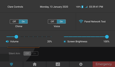
Quick settings menu display
Battery: The battery icon displays the panel’s current battery percentage.
Door Chime: The door chime On/Off buttons allow the user to enable/disable the panel’s chime when a sensor opens/closes.
Voice: The voice On/Off buttons allow the user to enable/disable the panel’s annunciations.
Wifi: The Wifi box displays the panel’s current WiFi status and connected network.
Volume: The volume slider displays and allows the user to adjust the panel’s current volume.
Screen Brightness: The screen brightness slider displays and allows the user to adjust the panel’s current brightness.
To access the quick settings menu:
- Tap and hold the status bar.
- Swipe downward.
To adjust the volume and brightness level:
- Access the quick settings menu.
- Tap and slide volume/screen brightness indicator left (decreases volume/brightness) or right (increases volume/brightness).
To enable/disable the door chime:
- Access the quick settings menu.
- Tap On/Off.
To enable/disable voice:
- Access the quick settings menu.
- Tap On/Off.
Full PDF - ClareOne Wireless Security and Smart Home Panel User Manual (DOC ID 1871)
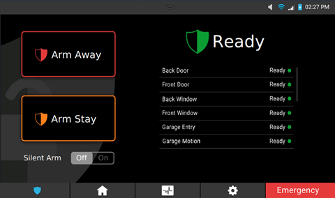
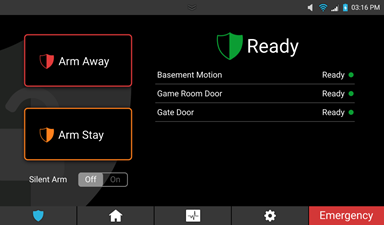
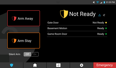
Security
The Security menu badge allows a user to quickly access their ClareHome security control and sensors. Immediately, users see the state of their security system and sensors.
Note: The security monitoring account must be created through the Clare Controls dealer.
Figure 11: Security
Security user management
The panel allows for individual users and a duress code. See User Management for full user creation and management information.
Operating security
The security panel allows the user to arm the panel in stay mode, arm the panel in away mode, disarm the panel, and contact their monitoring station in the case of an emergency.
Arming the panel
There are several things to note when arming the panel.
- The security system shall enunciate a distinct pulsating audible sound throughout the duration of the Exit Time to warn person(s) still within the premises that the exit period is in process.
An audible annunciation, whose pulsating rate is distinctly different, shall sound during the last 10 seconds of the Exit Time to warn person(s) that the Exit Time is running out.
The ClareOne panel supports Arm Stay and Arm Away (panel annunciation), and Silently Arm (no panel annunciation). When using Silently Arm, the exit time is doubled.
- Violation, restoral, and then a second violation of an entry/exit zone prior to the end of the Exit Time restarts the Exit Time. The panel does not allow the Exit Time to be restarted more than once. This feature is enabled by default. Duration of the additional Exit Time shall be doubled for that additional exit period only but shall not exceed 255 seconds.
- A distinct annunciation is produced upon entry to warn those entering the premises that the Entry Delay has started.
- The ClareHome application displays states for the panel (Armed, Disarmed, Alarmed, Sensors Faulted or Troubled). Refer to the ClareHome App Guide (DOC ID 1750) for additional information.
- The ClareHome application allows the user to Arm the ClareOne security panel from any remote location if internet service is available on the panel. Refer to the ClareHome App Guide (DOC ID 1750) for additional information.
- The siren sounds for up to 4 minutes if the panel has not been disarmed. After 4 minutes, the panel no longer sounds but remain in the alarm state.
To arm the panel:
- Tap the Security Badge icon
 .
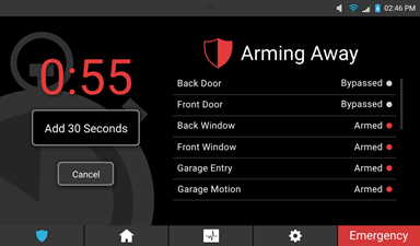
. - Tap Arm Away.
– or –
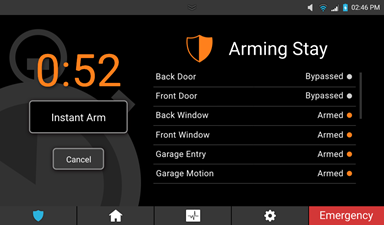
Tap Arm Stay.
Notes
- When selecting Arm Stay, the user has the option to instantly arm the panel.
- Tap Cancel to stop the arming process, this requires a user PIN.
- The device arms and must be disarmed using a set PIN.
Armed Stay

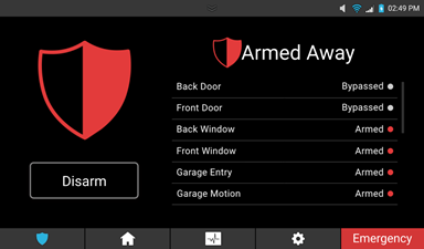
Armed Away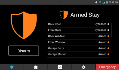
To bypass a zone:
Note: If a zone (sensor) is faulted (open), the panel cannot be armed until the zone is either no longer faulted, or the zone is bypassed.
- Tap the Security Badge icon
 .
. - Select an arming method (Arm Stay or Arm Away).
- Tap Confirm Bypass.
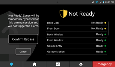
- The panel continues to arm as normal.
To arm the panel using a silent arm:
- Tap the Security Badge icon
 .
. - Tap the Silent arm On/Off button.
- Tap the desired arming method.
- The panel continues to arm silently.
Note: During a silent arm, the panel adds additional time and does not have an audible countdown (no beeps).
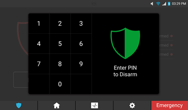
To disarm the panel:
- Tap the Security Badge icon
 .
. - Tap Disarm.
- Enter the PIN, and then tap Confirm.
To silence a trouble condition:
- Tap the Security Badge icon
 .
.
When there is a trouble condition active, the security tab displays a Trouble Badge and a Microphone icon
  .
.
- Tap the Badge icon
 to see a list of trouble conditions.
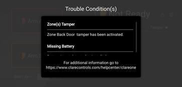
- Tap the Microphone icon
 , and then tap Silence to silence the trouble beeps for 12 hours.
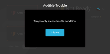
Full PDF - ClareOne Wireless Security and Smart Home Panel User Manual (DOC ID 1871)
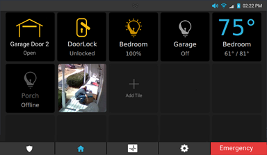
Favorites
The Favorites page allows the user to add frequently used device and Scene tiles to the panel.
Figure 12: Favorites

Notes
- When there are no favorites added to the page, only 3 rows display. Once an icon is added to the last space in a row, additional rows are added.
- Icons keep their position when icons around them are removed or added.
To add a tile to favorite:
- Tap an empty tile, and then tap the Plus icon.
- Tap the desired category.
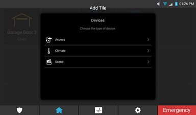
- Tap the Plus icon next to the desired device/Scene.
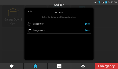
The icon is added to the screen.
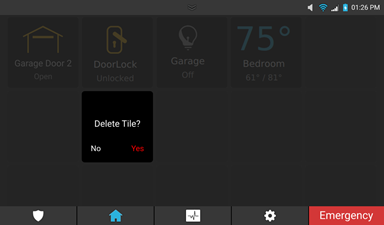
To remove a tile from favorite:
- Tap and hold the desired icon.
- Tap Yes.
Top of page ^
Full PDF - ClareOne Wireless Security and Smart Home Panel User Manual (DOC ID 1871)
Activity
The Activity page displays a list of the security events. This list includes the time and state or action of the panel (armed, disarmed, troubled, and faulted).
Note: The panel takes snapshots when activity occurs, or whenever a PIN code is entered. Tapping the snapshot enlarges the image.
Figure 13: Activity
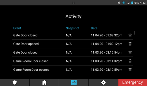
Table 4: ClareOne activity icons
|
Icon |
Name |
Description |
 |
Delete |
The delete icon allows the user to delete a security event from the activity list. |
To delete an event from the activity list:
- Tap the Delete icon
 .
.
The event is deleted.
Full PDF - ClareOne Wireless Security and Smart Home Panel User Manual (DOC ID 1871)
Settings
The Settings page allows the user access to modify panel settings.
Figure 14: Settings
The below items are setting options the user can view and modify.
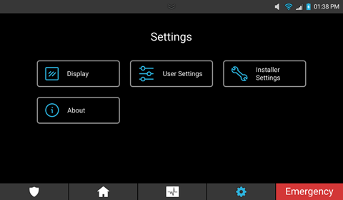
Display
The Display page allows the user access to adjust screen settings.
Figure 15: Display
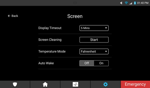
Display settings
Display Timeout: This setting allows the user to adjust the length of time before the screen times out.
Screen Cleaning: This setting allows the user 1 minute to clean the panel’s screen. During this time, the screen is not touch sensitive.
Temperature Mode: This setting allows the user to select Fahrenheit or Celsius for their thermostat display.
Auto Wake: This setting allows the user to use the panel’s PIR sensor to “wake” the panel from a time out. When set to Off, the panel does not “wake” when it senses motion.
User Settings
The User Settings page hosts a sub menu of user settings.
Note: The Master PIN is required to access User Settings.
Figure 16: User Settings

For full User Settings, see User and Installer Settings.
Installer Settings
The Installer Settings page hosts a sub menu of advanced settings.
Note: The Installer Settings page can only be accessed with the Installer PIN.
Figure 17: Installer Settings

For full Installer Settings, see User and Installer Settings.
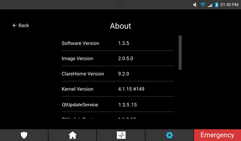
About
The About page displays panel specific information including the firmware, hardware versions, and network settings.
Figure 18: About
Full PDF - ClareOne Wireless Security and Smart Home Panel User Manual (DOC ID 1871)
User and Installer Settings
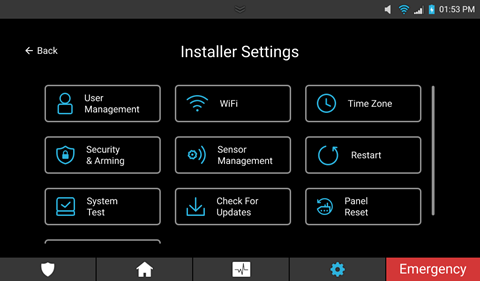
The User and Installer Settings pages are sub-menus of Settings. The User Settings page hosts settings for the master user and the Installer Settings page hosts advanced settings for the installer. The User Settings menu has access to User Management and the Installer Settings menu has access to Panel Reset, and Demo Mode. Both pages allow access to WiFi management, Time Zone Settings, Security & Arming, Sensor Management, Restart, System Test, and Check for Updates.
Figure 19: User Settings
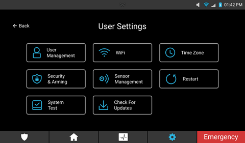
Figure 20: Installer Settings

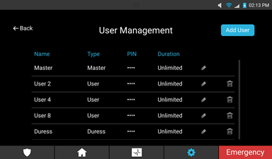
User Management
Note: User Management is only accessible in the User Settings menu.
The User Management page allows the user to add, modify, and remove panel users.
Figure 21: User Management

To add a user:
- Tap the Settings icon
 .
. - Tap User Settings, enter the master PIN, and then tap User Management.
– or –
Tap Installer Settings, enter the installer PIN, tap User Management, and then enter the master PIN.
- Tap Add User.
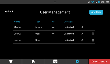
- Select User (there are 3 user types).
User types
Master: The master user has access to all User Settings and is set by default.
Note: The Master User can only be modified, a second master user cannot be added.
Duress Code: A user code that sends an emergency alert to the monitored central station.
Notes
- Only 1 duress code can be added to the panel.
- Duress is disabled by default. Once a Duress user is created, duress is enabled.
User: A basic panel user. This user has access to security controls and basic panel operation.

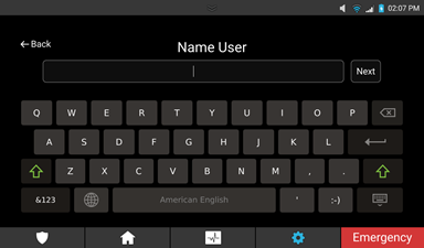
- Select the user’s name.
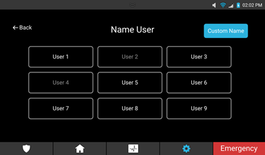
– or –
Tap Custom Name, enter the desired name, and then tap Next.
- Enter a user passcode, and then tap Next.
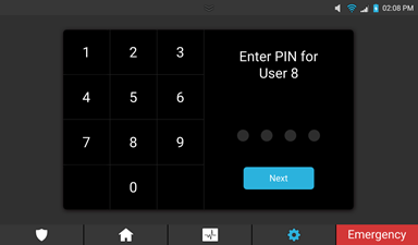
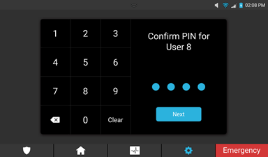
- Confirm the passcode, and then tap Next.
- Select the expiration date. (1 hour, 4 hours, 8 hours, 24 hours, 7 days, or unlimited).
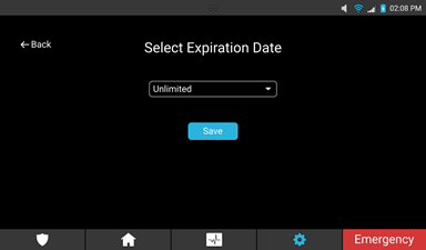
- Tap Save.
To create a duress code:
Notes
- Only 1 duress code can be added to the panel.
- Duress is disabled by default. Once a Duress user is created, duress is enabled.
- Tap the Settings icon
 .
. - Tap User Settings, enter the master PIN, and then tap User Management.
– or –
Tap Installer Settings, enter the installer PIN, tap User Management, and then enter the master PIN.
- Tap Add User.

- Select Duress Code.
Note: The ClareOne panel only supports one Duress user.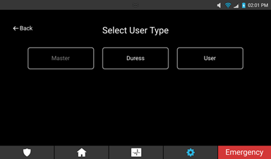
- Enter the desired code, and then tap Next.

- Confirm the passcode, and then tap Next.
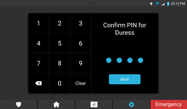
- Tap Save.
To modify a user/duress code:
- Access User Management.
Settings > User Settings >Enter master PIN > User Management
– or –
Settings > Installer Settings >Enter installer PIN > User Management > Enter master PIN
- Select the desired user/duress, and then tap the Edit User
 icon.
icon. 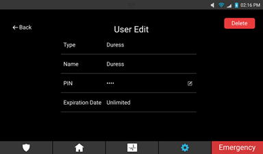
- Select the desired field to edit.
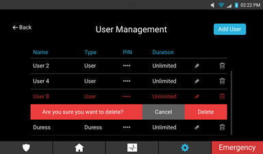
To remove a user:
- Access User Management.
Settings > User Settings >Enter master PIN > User Management
– or –
Settings > Installer Settings >Enter installer PIN > User Management > Enter master PIN

- Tap the Delete
 icon next to the desired user/duress.
 - Confirm by tapping Delete.
WiFi
The WiFi page allows the user/installer access to the available WiFi networks and their corresponding strengths.
Figure 22: WiFi
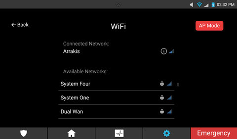
To change WiFi networks:
- Tap the Settings icon
 .
. - Tap User Settings, enter the master/installer PIN, and then tap User Management WiFi.
- Tap on the desired WiFi network, and then enter the password as prompted.
- Tap OK.
The panel is now on the desired WiFi network.
Note: Tap the Info icon next to the connected network to view specific information.
To set the panel to AP Mode:
AP Mode allows the user to set their panel in AP mode to use the Clare Controls Install Assist app. Once turned on, the user sees the panel’s broadcasted network and a randomized passcode.
Note: This passcode is random at each generation.
- Tap Settings, and then tap User Settings/Installer Settings.
- Enter the Master/Installer PIN, and then tap WiFi.
- Tap AP Mode, and then tap ON.
The panel is now in Ap mode.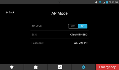
- Tap Off to exit AP mode and reconnect to the Local Area Network.
Time Zone
The Time Zone page allows the user/installer access to select/change the time zone.
Figure 23: Time Zone
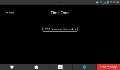
To select a time zone:
- Tap Settings, and then tap User Settings/Installer Settings.
- Enter the Master/Installer PIN, and then tap Time Zone.
- Tap the Select Time Zone drop-down.
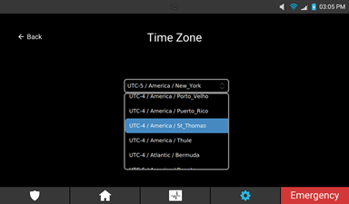
- Scroll up or down to set the desired zone, and then tap Save.
Security & Arming
The Security & Arming page allows the user/installer to modify security settings. Adjusting delay times, volume, and chime settings.
Note: These are advances settings, we only recommend adjusting them if the user/installer is familiar with security settings.
Figure 24: Security & Arming
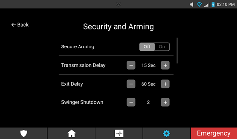
Security & Arming settings
Secure Arming: When enabled this setting requires that the user enter a PIN to arm the security panel.
Transmission Delay: The time in seconds that the panel waits if an alarm is triggered before sending a transmission to the security central station.
Exit Delay: The amount of time in seconds the panel waits for a user to exit the building before arming.
Swinger Shutdown: The number of times that the panel ignores a repeated sensor trigger during an egress (false alarm).
Cross Zoning: This setting links 2 or more sensors together. If one of the sensors is tripped, and another sensor in that cross zone is tripped within the set time, an alarm is triggered.
Voice: This setting adjusts whether the panel annunciates zone statuses.
Chime: This setting enables/disables chimes for zone entry.
Cancel Alarm: When Cancel Alarm is enabled, if the panel alarm is cancelled within 5 minutes, there is an audible alarm cancelled sound and a message is also sent to the central station saying that the alarm was canceled.
Tamper Enable: This setting enables/disables panel tamper.
Note: When this setting is disabled, the panel cannot be armed.
Auto Armed Stay: This setting enables/disables the ignore armed stay defaults. When enabled, armed away sets to arm stay if there is no egress.
To modify security and arming settings:
- Tap Settings, and then tap User Settings/Installer Settings.
- Enter the Master/Installer PIN, and then tap Security & Arming.
- Tap on the field +/- icon, or Off/On buttons.
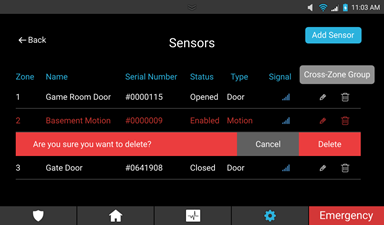
Sensor Management
The Sensor Management page allows the user/installer to add, modify, and remove panel sensors. For a full sensor list and individual sensor settings, see ClareOne Sensors Integration Notes (DOC ID 1931).
Figure 25: Sensor Management

To add a sensor:
- Tap Settings, and then tap User Settings/Installer Settings.
- Enter the Master/Installer PIN, and then tap Sensor Management.
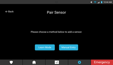
- Tap Add Sensor.

- Select the desired sensor add mode, Learn Mode or Manual Entry.
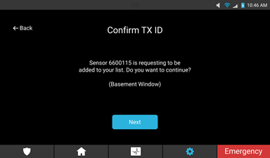
Learn Mode
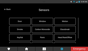
- Select Learn Mode.
- Select the type of sensor.
- Trip the physical sensor. For example, move the door’s sensor and magnet away from each other.
- Select a name for the sensor, and then configure any desired sensor features, and then tap Next.
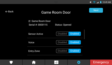
- Confirm the Sensor ID, and then tap Next.

Manual entry
- Select Manual Entry.

- Select the sensor type.

- Enter the TX ID, and then tap Next.
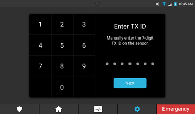
Note: This 7-digit ID is found on a sticker/label on the sensor.
-
Select a name for the sensor, configure any desired sensor features, and then tap Next.
-
Verify that the TX ID displayed matches the sensor, and then tap Next.
- Select Learn Mode.
To modify the sensor:
- Access Sensor Management. (Settings > User/Installer Settings > Enter user/installer PIN > Sensor Management).

- Tap the Edit Sensor
 icon.
icon. 
- Select the desired field to edit.
To remove a sensor:
- Access Sensor Management. (Settings > User/Installer Settings> Enter user/installer PIN > Sensor Management).

- Tap the Delete
 icon next to the desired sensor.
 - Confirm by tapping Delete.
To create the Cross-Zone Group:
Cross Zoning links 2 or more sensors together. If one of the sensors is tripped, and another sensor in that cross zone is tripped within the set time in this field, an alarm is triggered.
Note: This is an advanced feature. We do not recommend using this option unless familiar with it.
- Access Sensor Management. (Settings > User/Installer Settings > enter user/installer PIN > Sensor Management).

- Tap the Edit Sensor
 icon.
icon. 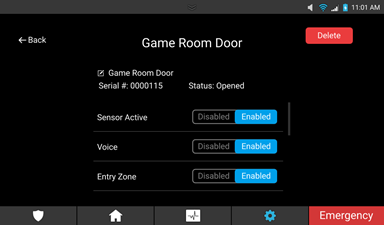
- Scroll down to view Cross-Zone, and then tap Enabled.
- Repeat steps 2 through 3 for each zone to be added to the cross-zone.
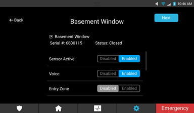
Modifying sensor settings
Each ClareOne sensor can be adjusted for user preference. Use the steps below to access Sensor Management. For full sensor setting information, see ClareOne Sensors Integration Notes (DOC ID 1931).
Note: These settings should not be adjusted without proper security experience and knowledge. Only modify these settings if you are familiar with them.
To modify a sensor’s settings:
- Access Sensor Management. (Settings > User/Installer Settings > Enter user/installer PIN > Sensor Management).

- Tap the Edit Sensor
 icon.
icon. 
- Select the desired field to edit.
Restart
The Restart button allows the user/installer to restart the ClareOne panel.
Note: During the restart, the panel is not functional. Alarms and sensors are not active.
Figure 26: Restart
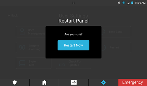
To restart the panel:
- Tap Settings, and then tap User Settings/Installer Settings.
- Enter the Master/Installer PIN, and then tap Restart.
Confirm by tapping Restart Now.
Full PDF - ClareOne Wireless Security and Smart Home Panel User Manual (DOC ID 1871)
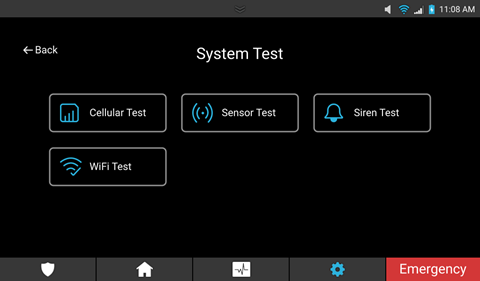
System Test
The System Test page allows the user/installer access to test different functions of the panel to help identify and correct problems. Run tests to verify that the panel is functioning correctly after final panel installation.
Notes
- The panel should be tested after installation as well as weekly to ensure proper function.
- When testing the panel, verify that the panel is powered by battery only. Unplug the panel from the wall outlet, and then perform the desired tests.
- Smoke detectors should always be checked monthly and after an alarm.
Figure 27: System test
To test the panel:
- Unplug the panel from the wall outlet.
- Look at the displayed panel state, verify that it is in normal standby mode with no current alarms.
- Fault/open one of the paired sensors.
The panel vocalizes that the sensor is not ready, and the faulted sensor is now marked not ready on the Security page. - Access the panel’s System Test page.
Settings > User/Installer Settings > Enter user/installer PIN > System Test - Tap and run the desired test. See the following tests list for test definition.
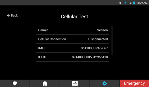
Cellular Test
The Cellular Test page displays the panel’s current cellular information.
Figure 28: Cellular Test
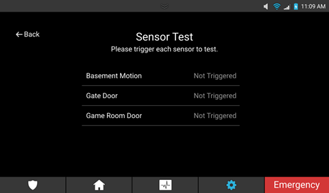
Sensor Test
The Sensor Test page allows the user to check each sensor on their system. Triggering the sensor verifies that the sensor is currently communicating with the panel.
Figure 29: Sensor Test
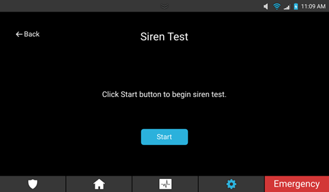
Siren Test
The Siren Test page allows the user to check that a siren is working.
Figure 30: Siren Test
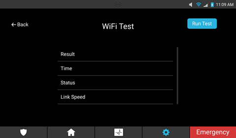
WiFi Test
The WiFi Test page allows the user/installer to see their connected WiFi and its status.
Note: This test may take up to 60 seconds.
Figure 32: WiFi Test
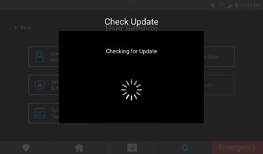
Check for Updates
The feature allows the user/installer the ability to check for panel updates. This is used when an update has been dismissed or if the user is unsure of their current panel firmware.
Notes:
- Check for updates is available in both User and Installer Settings.
- The panel auto-prompts the user to update when updates become available.
Figure 33: Check for Updates

To check for updates:
- Tap Settings, then tap User/Installer Settings.
- Enter the Master/Installer PIN as prompted.
- Tap Check for Updates.
Note: If the panel is up to date you are not prompted to update.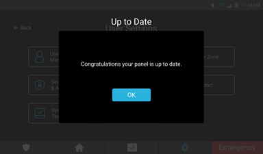
- Tap Update Now.
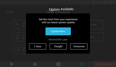
The update process begins.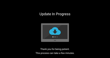
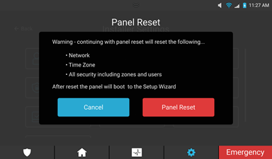
Panel Reset
This feature allows the user to default the panel.
Notes
- Panel Reset is only available in Installer Settings.
- When performing a panel reset, the panel loses all configured zones, users, and time zone settings.
Figure 34: Panel Reset
To reset the panel:
- Tap Settings, then tap Installer Settings.
- Enter the Installer PIN as prompted.
- Tap Panel Reset.
- Read through the warning popover, and then tap Panel Reset.
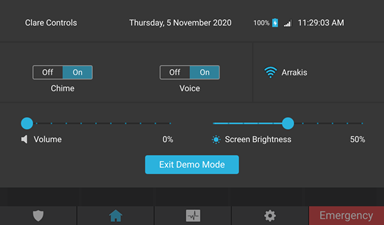
Demo Mode
The mode allows the user to see a working demo of the panel. The user can add and remove favorite tiles, manage security, and see events.
Note: Demo Mode is only available in Installer Settings.
Figure 35: Demo Mode

To enter Demo Mode:
- Tap Settings, then tap Installer Settings.
- Enter the Installer PIN as prompted.
- Tap Demo Mode.
- Tap tiles and icons to operate the corresponding devices.
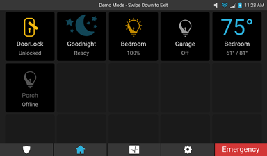
To exit Demo Mode:
- Swipe the top bar downward.
- Tap Exit Demo Mode, and then the panel restarts.
Full PDF - ClareOne Wireless Security and Smart Home Panel User Manual (DOC ID 1871)
Emergency
The Emergency button  is always available on the Menu bar. This button gives the user instant access to emergency options. Use this button to contact the monitored central call station for an emergency.
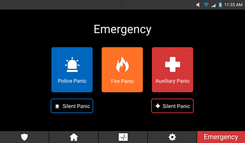
Figure 36: Emergency options

Pressing the button takes the user to the Emergency screen, shown in Figure 37: Emergency options. The user then selects their emergency type.
Emergency options
The Emergency screen features 3 options: Police Panic, Fire Panic, and Auxiliary Panic. The auxiliary and police emergencies also have a Silent Panic option.
The Silent Panic option allows the user to send an auxiliary or police panic without sound. This option returns the user to the home screen, and then they are contacted via phone by the monitored central call station.
Figure 37: Emergency options
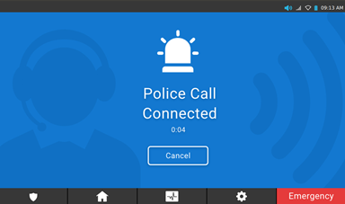
Police Panic
This button calls the monitored alarm station with a police emergency. Once pressed, it dials for the user. When the station answers, the screen changes, and the user can communicate with them through two-way voice.
Note: When the station is called using a silent panic, two-way communication is not available.
Figure 38: Emergency Police Panic
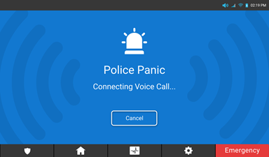
Figure 39: Emergency Police connection
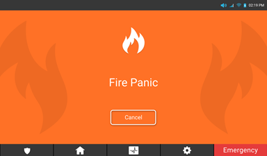
Fire Panic
This button sends an immediate fire panic to the central station.
Figure 40: Emergency Fire Panic
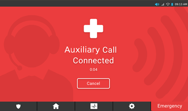
Auxiliary Panic
This button calls the monitored alarm station with an auxiliary emergency. Once pressed, it dials for the user. When the station answers, the screen changes, and the user can communicate with them through two-way voice.
Note: When the station is called using a silent panic, two-way communication is not available.
Figure 41: Emergency Auxiliary Panic
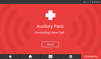
Figure 42: Emergency Auxiliary connection
Full PDF - ClareOne Wireless Security and Smart Home Panel User Manual (DOC ID 1871)
Basic operation
This section covers the basic operation of the ClareOne Panel, including terms and maintenance recommendations.
Panel states
The ClareOne Panel has multiple states. Each state has a different effect on the panel and user access.
Normal Standby: This is the normal state of the panel. In this state everything is accessible for the user/installer when using the proper PIN codes. No alarms or warnings are present.
Alarm: The panel is experiencing an alarm. The central station is notified according to transmission time defined in Security & Arming.
Note: The central station is only notified if the user has monitoring.
Alarm Test: The panel’s alarm should be tested regularly; it is recommended once a week. Use the Siren Test to check that the siren is working. See System Test. This test does not call alert the central station, it is a local test.
Trouble: The panel is currently experiencing a trouble condition. For example, a sensor battery is dead. For a list of all trouble conditions, see Trouble Conditions.
Trouble Silence: This silences the beeping due to the trouble state. Trouble Silence is in effect for 12 hours, and then the trouble beeping continues.
Panel LED
The ClareOne Panel features an LED at the bottom center, see Figure 1: ClareOne Panel. The LED reflects the state of the panel.
|
LED Color |
Panel State |
|
Green |
The Panel is a Ready State and can be armed. |
|
Yellow |
Panel is in trouble/not ready. |
|
Red |
Panel is in alarm. |
|
Blue |
Security has been armed or is being a armed during exit delay |
|
Off |
Panel is running on battery power or there is no power and the panel is off. |
Maintenance
The panel should be used and tested weekly. Testing should include validating communication between sensors and panel, verifying the alarm functions properly, validating operation on battery, and checking that communication networks are operational.
For panel and sensor testing, see System Test. For battery maintenance, see Panel battery specifications and maintenance.
Smoke detector considerations
The ClareOne panel does not have any direct wiring options to connect and monitor smoke detectors. The ClareOne Smoke Sensor uses wireless connectivity to the panel. Pressing the test button on the smoke sensor will sound the siren in the sensor as well as alert the panel. All smoke detectors should be regularly checked and tested. In the case of a low battery in the smoke sensor, a notification will be sent to the panel. For more details on testing the smoke sensor, refer to the smoke sensor’s manual.
WARNING: THIS UNIT INCLUDES AN ALARM VERIFICATION FEATURE THAT WILL RESULT IN A DELAY OF THE SYSTEM ALARM SIGNAL FROM THE INDICATED CIRCUITS. THE TOTAL DELAY (CONTROL UNIT PLUS SMOKE DETECTORS) SHALL NOT EXCEED 60 SECONDS. NO OTHER SMOKE DETECTOR SHALL BE CONNECTED TO THESE CIRCUITS.
AVERTISSEMENT: CET APPAREIL COMPREND UNE FONCTION DE VÉRIFICATION D'ALARME QUI RÉSULTERA PAR UN RETARD DU SIGNAL D'ALARME DU SYSTÈME DES CIRCUITS INDIQUÉS. LE RETARD TOTAL (UNITÉ DE COMMANDE PLUS DÉTECTEURS DE FUMÉE) NE DOIT PAS DÉPASSER 60 SECONDES. AUCUN AUTRE DÉTECTEUR DE FUMÉE NE SERA CONNU À CES CIRCUITS.
Contact
In the event of panel trouble, contact the local dealer or monitoring center listed below.
Local Dealer Phone Number: _______________________________
Local Dealer Email: _______________________________________
Monitoring Center Phone Number: ___________________________
If there is no information provided above, contact:
Clare Technical Services
941.404.1072
ClareSupport@clarecontrols.com
Full PDF - ClareOne Wireless Security and Smart Home Panel User Manual (DOC ID 1871)
Evacuation plan
It is recommended that everyone have an evacuation plan to get away safely in the event of a fire or emergency. Create an evacuation plan for safety. See the National Fire Protection Association’s (NFPA) evacuation information.
https://www.nfpa.org/Public-Education/Staying-safe/Preparedness/Escape-planning
NFPA has recommended the following planning tips and action plans:
Escape planning tips
- Pull together everyone in your household and make a plan. Walk through your home and inspect all possible exits and escape routes. Households with children should consider drawing a floor plan of your home, marking two ways out of each room, including windows and doors. Also, mark the location of each smoke alarm.
- A closed door may slow the spread of smoke, heat and fire. Install smoke alarms in every sleeping room, outside each sleeping area and on every level of the home. NFPA 72, National Fire Alarm Code® requires interconnected smoke alarms throughout the home. When one sounds, they all sound.
- When you walk through your plan, check to make sure the escape routes are clear and doors and windows can be opened easily.
- Choose an outside meeting place (i.e. neighbor's house, a light post, mailbox, or stop sign) a safe distance in front of your home where everyone can meet after they've escaped. Make sure to mark the location of the meeting place on your escape plan.
- Go outside to see if your street number is clearly visible from the road. If not, paint it on the curb or install house numbers to ensure that responding emergency personnel can find your home.
- Have everyone memorize the emergency phone number of the fire department. That way any member of the household can call from a neighbor's home or a cellular phone once safely outside.
- If there are infants, older adults, or family members with mobility limitations, make sure that someone is assigned to assist them in the fire drill and in the event of an emergency. Assign a backup person too, in case the designee is not home during the emergency.
If windows or doors in your home have security bars, make sure that the bars have emergency release devices inside so that they can be opened immediately in an emergency. Emergency release devices won't compromise your security - but they will increase your chances of safely escaping a home fire.
- Tell guests or visitors to your home about your family's fire escape plan. When staying overnight at other people's homes, ask about their escape plan. If they don't have a plan in place, offer to help them make one. This is especially important when children are permitted to attend "sleepovers" at friends' homes. See NFPA's "Sleepover fire safety for kids" fact sheet.
- Be fully prepared for a real fire: when a smoke alarm sounds, get out immediately. Residents of high-rise and apartment buildings may be safer "defending in place."
- Once you're out, stay out! Under no circumstances should you ever go back into a burning building. If someone is missing, inform the fire department dispatcher when you call. Firefighters have the skills and equipment to perform rescues.
Put your plan to the test
- Practice your home fire escape plan twice a year, making the drill as realistic as possible.
- Make arrangements in your plan for anyone in your home who has a disability.
- Allow children to master fire escape planning and practice before holding a fire drill at night when they are sleeping. The objective is to practice, not to frighten, so telling children there will be a drill before they go to bed can be as effective as a surprise drill.
- It's important to determine during the drill whether children and others can readily waken to the sound of the smoke alarm. If they fail to awaken, make sure that someone is assigned to wake them up as part of the drill and in a real emergency situation.
- If your home has two floors, every family member (including children) must be able to escape from the second floor rooms. Escape ladders can be placed in or near windows to provide an additional escape route. Review the manufacturer's instructions carefully so you'll be able to use a safety ladder in an emergency. Practice setting up the ladder from a first floor window to make sure you can do it correctly and quickly. Children should only practice with a grown-up, and only from a first-story window. Store the ladder near the window, in an easily accessible location. You don't want to have to search for it during a fire.
- Always choose the escape route that is safest – the one with the least amount of smoke and heat – but be prepared to escape under toxic smoke if necessary. When you do your fire drill, everyone in the family should practice getting low and going under the smoke to your exit.
- Closing doors on your way out slows the spread of fire, giving you more time to safely escape.
- In some cases, smoke or fire may prevent you from exiting your home or apartment building. To prepare for an emergency like this, practice "sealing yourself in for safety" as part of your home fire escape plan. Close all doors between you and the fire. Use duct tape or towels to seal the door cracks and cover air vents to keep smoke from coming in. If possible, open your windows at the top and bottom so fresh air can get in. Call the fire department to report your exact location. Wave a flashlight or light-colored cloth at the window to let the fire department know where you are located.
Full PDF - ClareOne Wireless Security and Smart Home Panel User Manual (DOC ID 1871)
Glossary
|
Term |
Definition |
|
Bypass |
A state used to arm the security system when a zone (sensor) is faulted (open). |
|
Duress code |
A code that sends an emergency alert to the monitored central call station. |
|
Cross zone |
This setting links 2 or more sensors together. If one of the sensors is tripped, and another sensor in that cross zone is tripped within the set time in this field, an alarm is sent. |
|
Faulted |
The state of a zone (sensor) that is open, low on battery, or in any state other than ready. |
|
Zone |
The name of a security sensor. |
Full PDF - ClareOne Wireless Security and Smart Home Panel User Manual (DOC ID 1871)
Appendices
The below items are included in the ClareOne manual for user convenience.
Quick reference
Trouble conditions
Panel zone list tracking
Sensor installations and specifications
Quick reference
The following information on the ClareOne panel is provided in quick reference form for user convenience.
Table 5: Quick reference
|
Feature |
Quick reference info |
|
Exit Delay |
Exit Delay is the time in seconds that the panel waits if an alarm is triggered before sending a transmission to the security central station. This feature can be found and modified in Security & Arming |
|
Exit Time Restart |
The Exit Time Restart feature allows the panel user time to correct any accidental zone openings during the alarm process. Exit time is automatically restarted if an entry zone is opened and closed 2 times during the exit delay. If the zone is still open when the exit delay expires, a zone alarm is triggered, and then the entry delay is initiated. If the panel is not disarmed during the abort window, an alarm is sent to the central station. |
|
Auto Armed Stay |
This setting enabled/disables the ignore armed stay defaults. When this feature is enabled, armed away sets to arm stay if there is no egress (exit via an entry zone). This feature can be found and modified in Security & Arming |
|
Entry Delay |
Entry Delay is the time in seconds that the panel waits when an alarm is triggered for the panel to be disarmed before sending a transmission to the security central station. This feature can be found and modified in Sensor Management |
|
Progress Annunciation (enter) |
An audible alert is provided upon entering the premises through an entry zone while the panel is armed. The panel must be disarmed within the entry delay window or the alarm is sent to the central station. |
|
System Acknowledgement |
The ClareOne security widget/icon must be added to the ClareHome app’s Favorites/Home page in order to view ClareOne alarm panel status. Refer to the ClareHome App Guide (DOC ID 1750) for additional information. |
|
Remote Arming |
The ClareOne security widget/icon must be added to the ClareHome app’s Favorites/Home page in order to remotely arm the ClareOne security panel. Refer to the ClareHome App Guide (DOC ID 1750) for additional information. |
|
Transmission Delay |
The time in seconds that the panel waits when an alarm is triggered before sending a transmission to the security central station. This feature can be found and modified in Security & Arming |
|
Disarm (abort) |
Alarms may be silenced by entering a single user PIN. The panel alarm silences after entering the first PIN digit but will resume if PIN entry is aborted. Refer to Operating Security on page 22. |
|
Use of duress feature |
This feature enables/disables the ability to use a duress code. Duress codes may still be created in User Settings. This feature can be found and modified in Security & Arming |
|
Duress Code |
Master PIN users may create, edit or delete the Duress user. Only one duress user PIN is allowed. Ensure Duress Code operation is enabled in Security and Arming settings, it is disabled by default. This feature can be found and modified in Sensor Management |
|
Cross Zoning |
Links 2 or more sensors together. If one of the sensors is tripped, and another sensor in that cross zone is tripped within the set time in this field, an alarm is triggered. This feature can be found and enabled/disabled in Security & Arming |
|
Swinger Shutdown |
The number of times that the panel ignores a repeated sensor trigger during an egress (false alarm). This feature can be found and modified in Security & Arming |
|
Fire Alarms |
Fire verification is done in the available ClareOne smoke detector. Under normal condition, the sensor checks the chamber every 4 seconds for smoke. Upon the first instance of smoke detection, the sensor doubles the frequency that it checks the chamber to every 2 seconds. The smoke sensor sounds the siren and triggers an alarm within 10 seconds of reaching the mandated alarm levels. |
|
System Test |
System Test
|
Trouble conditions
This is a list of all possible trouble conditions for the panel and zones/sensors.
Table 6: Trouble conditions
|
Condition |
Description |
Audible alert |
|
Zone(s) Low Battery |
The sensor/zone has a low battery. |
“Zones low battery” |
|
Missing Battery |
The panel battery is not detected or installed. |
“No battery” |
|
CS Comm Fail |
Communication to the alarm monitoring station is lost. |
“CS comm fail” |
|
Panel Wall Tamper |
The panel’s tamper has been activated. |
“Panel wall tamper” |
|
Zone(s) Tamper |
The zone’s/sensor’s tamper has been activated. |
“Zones tamper” |
|
Zone(s) Alarm |
One or more zone/sensor is in an alarm. |
Siren sound |
|
AC Power Fail |
AC power is lost/disconnected. |
“AC power fail” |
|
Panel Low Battery |
The panel’s battery charge is low. |
“Panel low battery” |
|
Ethernet Trouble |
Ethernet or WiFi connection is lost. |
“Ethernet trouble” |
|
Zone(s) Trouble |
The zone/sensor has lost communication with the panel. |
“Zone Lost Supervisory” |
Panel zone list tracking
Print these pages out for the installer to use for panel zone tracking. For a separate copy of this sheet, see ClareOne Panel Zone Tracking (DOC ID 1930).
|
Zone # |
Name |
Zone # |
Name |
|
1 |
|
31 |
|
|
2 |
|
32 |
|
|
3 |
|
33 |
|
|
4 |
|
34 |
|
|
5 |
|
35 |
|
|
6 |
|
36 |
|
|
7 |
|
37 |
|
|
8 |
|
38 |
|
|
9 |
|
39 |
|
|
10 |
|
40 |
|
|
11 |
|
41 |
|
|
12 |
|
42 |
|
|
13 |
|
43 |
|
|
14 |
|
44 |
|
|
15 |
|
45 |
|
|
16 |
|
46 |
|
|
17 |
|
47 |
|
|
18 |
|
48 |
|
|
19 |
|
49 |
|
|
20 |
|
50 |
|
|
21 |
|
51 |
|
|
22 |
|
52 |
|
|
23 |
|
53 |
|
|
24 |
|
54 |
|
|
25 |
|
55 |
|
|
26 |
|
56 |
|
|
27 |
|
57 |
|
|
28 |
|
58 |
|
|
29 |
|
59 |
|
|
30 |
|
60 |
|
|
61 |
|
95 |
|
|
62 |
|
96 |
|
|
63 |
|
97 |
|
|
64 |
|
98 |
|
|
65 |
|
99 |
|
|
66 |
|
100 |
|
|
67 |
|
101 |
|
|
68 |
|
102 |
|
|
69 |
|
103 |
|
|
70 |
|
104 |
|
|
71 |
|
105 |
|
|
72 |
|
106 |
|
|
73 |
|
107 |
|
|
74 |
|
108 |
|
|
75 |
|
109 |
|
|
76 |
|
110 |
|
|
77 |
|
111 |
|
|
78 |
|
112 |
|
|
79 |
|
113 |
|
|
80 |
|
114 |
|
|
81 |
|
115 |
|
|
82 |
|
116 |
|
|
83 |
|
117 |
|
|
84 |
|
118 |
|
|
85 |
|
119 |
|
|
86 |
|
120 |
|
|
87 |
|
121 |
|
|
88 |
|
122 |
|
|
89 |
|
123 |
|
|
90 |
|
124 |
|
|
91 |
|
125 |
|
|
92 |
|
126 |
|
|
93 |
|
127 |
|
|
94 |
|
128 |
|
Sensor installations and specifications
Note: The maximum distance over which a sensor and the panel can communicate may be reduced when the equipment is installed in a typical home. Placement of the sensor, building materials and construction, location of mirrors and other RF interfering/blocking devices can all reduce the overall range. It is best to test stationary sensors (door/window, motion, CO, smoke, etc.) with the panel at their actual installation location in order to make sure they will function properly before final installation is complete. The panel provides feedback on the signal strength of a sensor, which can be found under the Sensor Management screen, as shown below.
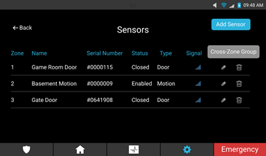
It is recommended that sensors have at least 3 bars of signal strength in their final installation location. If you are not able to achieve at least 1 bar, try to reposition the sensor and check environmental variables to achieve a better signal strength. Mirrors, glass, and appliances between the sensor and the panel can all affect signal strength. Anything in the way of direct line of sight shortens the length the signal can reliably travel. Objects have different impacts on the signal depending on their material. Some materials are easier to pass through – for example, plaster is easier to penetrate than metal foil.
See the full PDF.