What is the ClareOne panel?
The ClareOne Wireless Security and Smart Home Panel (CLR-C1-PNL1) is a smart home hub featuring customizable home automation and security control. ClareOne eliminates the need for separate control and customization devices.
In the box:
Note: Ensure all accessories are included. If not, contact the dealer.
- 1 x ClareOne panel (CLR-C1-PNL1)
- 1 x Battery (CLR-C1-BATT, located inside battery compartment of the panel)
- 1 x Wall mount bracket and Kickstand (CLR-C1-STND)
- 1 x Power supply (CLR-C1-12V)
- 1 x USB-C Ethernet adapter (CLR-C1-ETH)
- 1 x ClareOne Quick Start Guide (DOC ID 1885)
- Mounting hardware (screws and wall anchors)
- 1 x ClareOne bezel – white (CLR-C1-BZL-W)
- 1 x ClareOne bezel – black (CLR-C1-BZL-B, attached to panel)
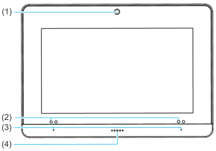
ClareOne Panel - front
|
(1) Camera |
|
(3) Microphones (on each side) |
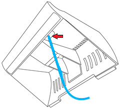
ClareOne Panel - exterior rear

|
(1) Tamper button |
|
(6) DC routing hole #1 |
Installation
Only qualified installation technicians should install the panel. Clare Controls does not assume responsibility for damages caused by improper installation, connection to the network, or use of the device.
Installation options
The ClareOne panel can be installed using a desktop stand or a wall mount. See the full manual for power supply options, ClareOne Wireless Security and Smart Home Panel User Manual (DOC ID 1871).
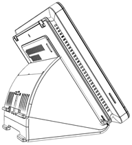
Installation option 1: Desktop
Option 1 uses the included kickstand.
To desktop mount the panel:
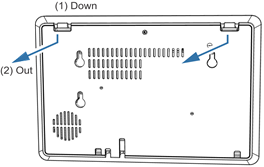
- Remove the panel’s back plate by pressing down on the 2 tabs and pulling the back plate outward, exposing the battery.

- Route the power supply cable through the hole in the bottom right side of the kickstand.
- Verify that the battery is plugged in, and then attach the power supply to the panel.
Note: For other power options, see Power supply options.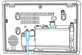
- Attach the panel’s back cover, gently pressing it into place. Verify that the tabs are both fully pressed in.
- Press the sides of the back plate against the back of the panel, making sure there is no gap between the back plate and the panel.
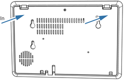
- Align the mounting holes in the back of the panel with the stubs on the kickstand, and then press kickstand to the rear of the panel.
- Slide the panel down, locking it into place.
- Plug the opposite end of the power supply into an electrical outlet.
The panel automatically powers up.
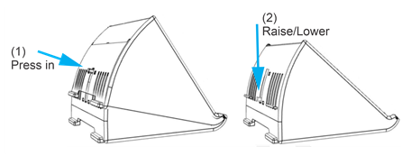
Note: Do not connect to a receptacle controlled by a switch. - (Optional) The viewing angle of the panel can be adjusted by pressing the kickstand tab and sliding the base up or down to the desired position, locking it into place.
Installation option 2: Wall mounted
Option 2 uses the included wall mount bracket. The recommended height for mounting the panel is 48 in. +/- 12 in. based on the comfort level of the end user.
To wall mount the panel:
- Select a location for the panel that is close to an outlet, and then run a connection from the 12VDC supply to the selected installation location.
- Place the mounting bracket against the selected wall location or gang box, ensuring that the power cable goes through the center of the mounting bracket.
Note: The cable does not need to go through the mounting bracket if the power cable does not run through the wall. - Using included screws securely attach the bracket to the gang box or wall. See the methods below.
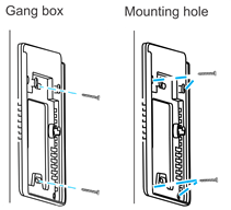
a. Gang box: Using 2 of the included machine screws, secure the bracket to the existing gang box.
b. Mounting hole: Mark the locations of the 4 holes in the wall mount bracket on the wall, be sure to keep the bracket level when marking the locations. Using a power drill with 5 mm bit, drill a hole at each location. Insert one of the included wall anchors into each of the 4 holes. Match the wall mount bracket to the anchor locations. Secure the panel to the wall using the provided screws in the 4 holes. - Remove the panel’s back plate by pressing down on the 2 tabs and pulling the back plate outward.
- Verify that the battery is plugged in, and then attach the power supply to the panel.

- Attach the panel’s back cover, gently pressing it into place.
- Press the sides of the back plate against the back of the panel, making sure there is no gap between the back plate and the panel.
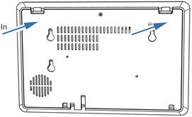
- Press the panel onto the mounting bracket, and then slide the panel down until it locks into place.
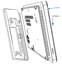
- Plug the opposite end of the power supply into an electrical outlet.
The panel automatically powers up.
Note: Do not connect to a receptacle controlled by a switch.
ClareOne setup wizard
The ClareOne panel has the ClareHome app pre-installed. Follow the setup wizard to connect to the home’s WiFi and add sensors.
To setup the panel:
- Tap the screen.
The Set Up Wizard displays.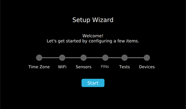
- Tap Start.
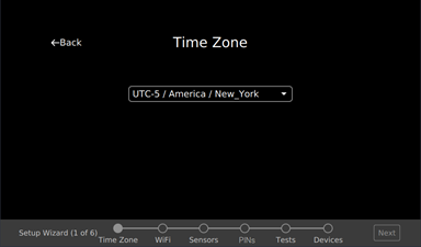
- Select the time zone from the drop-down, and then tap Next.
Notes
- ClareHome uses the location of the device for timers and events.
- Tap <- Back to return to the previous step/screen.
- Scroll and tap to select the desired network, enter the password, and then tap Ok.
Note: Tap
 to hide the keyboard.
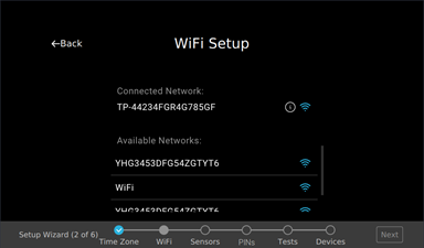
- Add the desired sensors. For full sensor configuration and management, see the full manual.
- Tap Next to continue in the wizard.
- Configure the Installer and Master PINs.
Notes
- The Installer PIN must be 5-digits and the Master PIN must be 4-digits.
- If the Master/Installer PINs are lost, the user cannot access Master/Installer menus or features. Do not forget these codes.
- Tap Set Installer PIN, and then enter the desired 5-digit PIN.
- Verify the PIN, and then tap Next.Configure the Installer and Master PINs.
You are returned to the Set PIN page.
-
Tap Set Master PIN, and then enter the desired 4-digit PIN.
-
Verify the PIN, and then tap Next.
You are returned to the Set PIN page. -
Tap Next to continue the wizard.
- Run any desired diagnostic tests, and then tap Next.
Note: Once installation is complete test the panel and sensors. - Add desired Z-Wave devices to the panel.
a. Tap Start.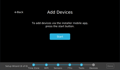
b. Connect to the project using the Clare mobile app.
For full device addition and configuration, see the ClareHome App Guide (DOC ID 1750). - Tap Finish.