/sensor.png?width=150&name=sensor.png)
Description
The Door/Window Sensor with Extended Contact is a supervised, wireless sensor that detects the opening and closing of doors/windows. The sensor and magnet are mounted using the included screws or double-sided adhesive tape.
When activated, the sensor transmits an open (trip) or close (restore) signal to the panel. These are the signals the unit provides: supervisory, tamper and low battery (as needed). The sensor is powered by (2) replaceable 3-VDC, lithium coin-cell batteries.
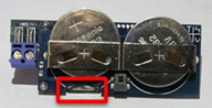
Figure 1: Sensor interior
/internal.png?width=336&name=internal.png)
External contact
An external contact can be connected to the transmitter by feeding contact wiring through the housing.
Figure 2: External contact
/connection.png?width=260&name=connection.png)
Notes
- Do not exceed 50 ft when wring to an external contact.
- Only one set of contacts can be used at one time: internal or external.
- For added security the internal reed switch can be cut.
- The Takeover setting, currently exposed on the ClareOne zone settings, must be enabled to use the external contact. It bypasses the reed magnet contact on the main sensor.
- The Normally Open setting is enabled when the external contact device is a normally open contact.
Installation
When installing the sensor abide by the following guidelines.
- Remove the transmitter’s cover by pressing in on the small rectangular latch on the end of the cover and lift up.
- Mount the sensor base directly to the surface using the mounting tape provided. Make sure to align the mounting tape with the tamper pull put area on the bottom of the sensor to insure proper tamper operation.
- Mount the magnet next to the sensor and align the magnet with the mark on the side of the sensor, using the mounting tape provided, or connect an external contact to the terminals.
- Remove the battery isolator tabs from both batteries on the sensor.
- Replace the cover on the transmitter.
- Program the sensor, and then test it.
Programming
To add the sensor to your panel and for detailed programming instructions, please refer to the ClareOne Wireless Security and Smart Home Panel User Manual (DOC ID 1871).
To add the sensor to the panel:
- Put the ClareOne panel in “add mode” and follow the displayed instructions for adding the sensor.
- Pull the magnet away from the sensor body.
- Or -
Open the sensor body case to tamper.
- Exit "add mode", and then adjust the sensors settings.
To configure the sensors to use external contact:
- Access sensor’s settings in panel.
Settings > User/Installer Settings > Sensor Management - Scroll to view Takeover, and then set it to “Yes”.
- Scroll to view Contact Normally, and then select the desired contact type (Closed/Open).
Modify the setting to reflect the proper configuration of the contact - If while the physical contact is in the normal (not faulted state) it shows faulted on the panel, toggle this setting to opposite of the current setting (If closed, toggle to open and vice versa).
Notes
-
- The Contact Normally setting can be adjusted either on the panel or in FusionPro.
- The sensor does not “learn” the faulted/not faulted condition of the contact and may need to be adjusted according to the condition reflected on the panel.
Testing the sensor
- Set the panel to the sensor test mode. See the full ClareOne Panel manual.
- Take the sensor and magnet to the desired mounting location, making sure to line up their alignment marks with each other. Trip the sensor by pulling the magnet away from the sensor, or by opening/closing the attached external contact.
- Monitor the system after tripping the sensor.
Note: If a low battery alarm occurs, replace the battery within 7 days.
CAUTION: Battery may explode if mistreated. Do not recharge, disassemble, or dispose of in fire.
Mounting the sensor
Mount the sensor using the supplied mounting screws for permanent mounting installations or (optional) using the supplied double-sided tape.
Note: The gap between the sensor and magnet should not exceed a maximum of .38 in (9.65 mm).
The center of the magnet will align with the arrow which is embossed on the side of sensor's main body (the location of the arrow will vary by sensor type).
For additional tamper security
Punch out the tamper cover on the bottom of the sensor, and using the small screw secure it to the mounting location, when the sensor is removed “tampered” the tab remains providing a tamper condition.
Specifications
|
Compatible panel |
ClareOne (CLR-C1-PNL1) |
|
Transmitter frequency |
433MHz |
|
Encrypted |
Yes |
|
Operating gap |
0.38 in (9.65 mm) |
|
Transmitted indications |
Tamper and low battery |
|
Supervisory keep-alive |
60 to 70 minutes |
|
Switch type |
Open loop (external contact) |
|
Battery type |
(2x) CR2032 |
|
Battery life |
8 to 10 years |
|
Operating environment Temperature |
|
|
Sensor dimensions |
2.75 × 1.00 × 0.50 in. |
|
Magnet dimensions |
1.5 × 0.5 × 0.44 in. |
|
Water resistant |
No |
|
Certifications |
FCC: 15.109 Class B 15.231, Industry Canada: ICES-003, RSS-210 |
Full PDF - ClareOne Door Window Sensor with External Contact Installation Sheet (DOC ID 1943)