Last modified: 11/05/20
Part number: CLR-C1-WD16
Description
The ClareOne 16 Zone Hardwired Input Module (HWIM) allows the takeover of hardwired security zones making them compatible with the ClareOne panel. The HWIM has
16 wired zone inputs each with LED status, a tamper switch input, a back-up battery charging terminal, and 2 auxiliary power outputs for powered sensors, capable of outputting 500mA @ 12VDC. The HWIM supports powered and unpowered sensors, including contact zones (open/close), motion sensors, and glass break detectors. Input zones 1 and 2 have an optional 2-minute communication time delay which can be enabled to prevent repeated signals from motion sensors being sent to the panel.
Once all sensors are wired to the HWIM, the HWIM and each zone can be paired to the ClareOne panel. Follow the steps in this installation sheet for HWIM and sensor connection to the panel.
Notes
- This wireless HWIM works with most wired sensors that do not require a smoke loop.
- Sensors/zones must be in their normally closed state when added to the HWIM.
Important safety instructions
- Before you install this HWIM, be sure to read, keep, and follow all instructions.
- When using a supervised back up battery, if the battery is low, replace it with a compatible lead-acid rechargeable battery.
Installation
Use the included screws for installation. The included antennas should be used regardless of location, for optimal RF communication.
Note: If the HWIM is being installed in a metal container or equipment rack, the antennas must extend outside the container to ensure that the RF communication is not interrupted. Do not bend or alter the antennas.
To install the HWIM:
- Carefully select the mounting location, verifying that the HWIM’s antennas are pointing up, and then secure it in position using the provided screws and wall anchors.
Note: The HWIM should be within 1000 ft (304.8 m) of the panel. Walls, construction materials, and other objects may impede the signal and shorten the distance. - Attach each antenna to the HWIM, placing one in each of the ANT terminals on the top of the HWIM.
Note: The antennas should be clear of obstructions and if in a metal enclosure, should extend outside of it. - Wire the sensors/leads to the desired terminals marked Zone 1 through 16.
Wiring notes:- The HWIM requires 4.7 kΩ of end of line (EOL) resistance on each zone. Existing installations may already have EOL resistors installed. Determine the current EOL resistance value and adjust as needed to get total resistance to 4.7 kΩ.
- EOL resistor installation depends on if the sensor is normally open (N/O) or normally closed (N/C). Refer to “Determining EOL resistance and sensor type” , for details on determining EOL resistance and if a sensor is N/O or N/C.
- Install one of the included 4.7 kΩ resistors to each zone with an attached sensor. Install the resistor in parallel for N/O and in series with N/C sensors.
- To provide power to powered sensors, such as motion and glass break sensors, wire the Positive and Negative leads from the sensor to the “AUX” (+) and “GND” (-) terminals. See Figures 1 and 2.
- Wire the tamper switch input.
Notes- If using a tamper switch, wire it directly to the tamper terminals without the need for an EOL resistor.
- If not using a tamper switch, simply connect a short piece of wire across the tamper input.
- (Recommended) For any security system that is supervised, a battery should be connected to the HWIM. To provide an independent battery back up to the HWIM, connect the included battery leads to a 12VDC, 5Ah lead acid rechargeable battery (battery not included). This battery type is common with traditional hardwired security panels, otherwise it is recommended that you connect the HWIM to an auxiliary 16VDC power supply (1 amp or greater) with its own battery backup.
- Connect the power supply leads from the provided power supply to the terminals labeled +16.0V and GND on the HWIM.
Note: The dashed wire is positive. - Plug the power supply into a 120VAC outlet.
Note: Do not plug the HWIM into a receptacle controlled by a switch.
Programming
The following instructions step through pairing the HWIM to the ClareOne panel.
Note: The CLR-C1-WD16 hardwired input HWIM must be paired with the ClareOne panel to ensure proper system operation.
Caution: For systems with motion sensors
When pairing a zone, tripping any motion sensor that is not already paired to the ClareOne panel causes the motion sensor to pair in instead of the target zone. This includes pairing in the HWIM. We recommend pairing in motion sensors before pairing in the HWIM or other sensors. This includes wired and wireless motion sensors.
To add the HWIM to the panel:
- Once the HWIM is powered on, open the front cover.
- Press and hold the Pair button on the HWIM for 2 seconds. All zone LEDs flash and extinguish. The Pairing LED illuminates, indicating that the HWIM is in “Pairing” mode.
- Access the ClareOne panel’s Sensor Settings (Settings > Installer Settings > Sensor Management > Add Sensor), and then select "Wired Input Module" as the device type. For detailed programming instructions, refer to the ClareOne Wireless Security and Smart Home Panel User Manual (DOC ID 1871).
- Trip the tamper input, either by opening the tamper switch, or removing the jumper across the inputs. Refer to “To install the WHIM,” step 4, on page 2. Once complete, close the tamper switch or replace the jumper.
- Follow the ClareOne panel on-screen prompts to complete the process.
Note: While a battery backup is recommended, if not adding a battery backup, disable the low battery notifications. To do this, access the HWIM’s sensor settings on the ClareOne panel and set “Low Battery Detection” to Off.
To pair the zones:
Notes
- Each zone must be paired individually, one at a time.
- If using a motion sensor, it is recommended to connect it to Zone 1 or 2, and then enable the communication delay for that zone. If using more than 2 hardwired motions, allocate the most active areas on these zones. The exception would be if using motions in an occupancy detection mode for automation, in which case this setting should not be enabled, or a different zone should be used for that motion sensor.
- Motion sensors should be paired first. This includes both wired and wireless motion sensors.
- If using motion sensors, complete steps 1 through 3 of “To add the HWIM to the panel” before continuing.
- Verify that the HWIM’s Pairing LED is illuminated.
If the LED is no longer illuminated, press and hold the Pair button for 2 seconds. - Put the ClareOne panel into “Pairing” mode.
- Trip the desired hardwired zone. Once a zone is tripped, its zone LED illuminates and remains lit until the HWIM exits “Pairing” mode.
To enable communication delay for Zone 1 or 2:- Before tripping another sensor press the Memory Reset button.
- The zone’s DLY LED illuminates, signifying that the 2-minute communication timer delay is enabled for that zone.
- Follow the ClareOne panel on-screen prompts to complete the process.
- Repeat steps 2 through 5 for each zone.
- Once all zones are paired, press the Pair button. The Pairing LED extinguishes, signifying the HWIM is no longer in “Pairing” mode.
Note: The HWIM must be taken out of “Pairing” mode before continuing.
Buttons and LEDs
The following section details the HWIM’s buttons and LEDs.
Buttons
Pair: The Pair button puts the HWIM in/out of “Pairing” mode.
Memory Reset: The Memory Reset button clears the HWIM’s memory and returns it to the factory default settings. The Memory Reset button is also used to enable/disable the communication timer delay for Zones 1 and 2.
To clear the memory:
- Remove power from the HWIM.
- Press and hold the Memory Reset
- Reapply power while continuing to hold the Memory Reset button.
- After 3 seconds, release the Memory Reset button.
The Processor, RF XMIT, and Pairing LEDs flash, indicating the HWIM is reset.
To enable communication timer delay on zones 1 or 2:
- Pair a sensor to zone 1 or 2.
Note: Complete the next step before adding another sensor. - Press the Memory Reset button.
The zone’s yellow LED illuminates, signifying that the 2-minute communication timer delay is enabled for that zone.
To disable communication timer delay on zones 1 or 2:
- Enter “Pairing” mode.
- Trip the sensor on zone 1 or 2, and then immediately press the Memory Reset
The zone’s yellow DLY LED extinguishes signifying that the lockout delay is disabled for the zone.
LEDs
Processor LED (red color): The Processor LED flashes to indicate processor operation.
RF XMIT LED (green color): The RF XMIT LED illuminates when RF transmission is sent.
Pairing LED (red color): The Pairing LED illuminates when the HWIM is in “Pairing” mode and is extinguished when the HWIM is in “Normal” mode. If there are no zones paired the Pairing LED flashes.
Note: The Pairing LED must be extinguished (not in “Pairing” mode) when testing sensors.
Zone LEDs (red color): During "Normal Operation Mode" each LED remains off until its corresponding zone is opened, then the LED illuminates. When entering "Pairing Mode" each zone LED flashes briefly, after which each zone LED remains off until the zone is learned in. Once learned in, it illuminates until "Pairing Mode" is complete.
DLY LEDs (yellow color): Zones 1 and 2 each have a DLY LED. When a zone’s DLY LED is illuminated yellow, that zone has the 2-minute communication timer delay enabled. When the DLY LED is off, that zone’s communication timer delay is disabled. When the DLY LED flashes, the associated zone has been tripped, and the 2-minute communication timer delay is in effect. All additional triggers from that sensor are ignored for 2 minutes. We recommend using zones 1 and 2 for motion sensors. For more information, see Programming.
Testing the HWIM
Once the HWIM is installed and programmed with all sensors paired, the system should be tested to verify that the HWIM and zones are working correctly.
To test the HWIM:
- Set the ClareOne panel to “Sensor Test” mode (Settings > Installer Settings > System Test > Sensor Test).
- Trip each zone on the HWIM one at a time. Monitor the system after tripping the zones. Refer to the ClareOne Wireless Security and Smart Home Panel User Manual (DOC ID 1871) for specific test information.
Determining EOL resistance and sensor type
Sometimes, it is not visually apparent what is physically connected to a zone in terms of pre-existing EOL resistors and whether the sensor is N/O or N/C. Use a multimeter to learn this information.
With a sensor in its active state (i.e. door/window contact separated from its magnet), take a multimeter set to measure resistance and connect the multimeter across the zone wires. If the multimeter reads a value of 10 kΩ or less, the sensor is N/O. If the multimeter reads an open or extremely high resistance (1 MΩ or higher) then the sensor is N/C. The table below provides guidance for using the measurements to determine the EOL resistance value, as well as the line resistance for N/O sensors. This is the case regardless of the number of sensors connected to a single zone, so long as all sensors on the same zone are in series or in parallel with one another.
Note: The HWIM will not work if there is a combination of series and parallel sensors connected to the same input zone.
|
|
Multimeter reads for N/O |
Multimeter reads for N/C |
|
Sensors active (sensor away from the magnet) |
Value for EOL resistor |
Open |
|
Sensors inactive (Sensors connected to the magnet) |
Value of line resistance (10 Ω or less) |
Value of EOL resistor plus line resistance |
EOL resistance on existing installations typically ranges from
1 kΩ – 10 kΩ while line resistance should be 10 Ω or less. However, some installations do not have any EOL resistors installed and the measured EOL resistance may be the same as the line resistance. If there are no EOL resistors installed, install the provided 4.7 kΩ resistor. Ideally, any existing EOL resistors would be removed and replaced with a 4.7 kΩ resistor. If that is not an option, additional resistors must be added, to get the EOL resistance to 4.7 kΩ.
For more information, refer to the ClareOne 16 Zone Wired Input Manual (DOC ID 1992).
Wiring
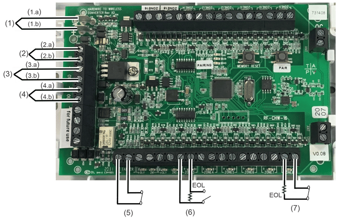
The graphic below details the HWIM wiring.
Figure 1: Wiring diagram
|
(1) 12 VDC Backup battery connection (2) 16 VDC Power supply connection (3) 12VDC Auxiliary Power Output 1 |
(4) 12VDC Auxiliary Power Output 2 (5) Tamper input (6) Wired zone N/O loop (7) Wired zone N/C loop |
Figure 2: Wiring a powered sensor
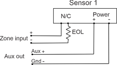
Note: When wiring a sensor that also has a tamper output, the alarm output and tamper output should be wired in series so that the zone will trigger on either a motion or tamper event.
Specifications
|
Compatible panel |
ClareOne (CLR-C1-PNL1) |
|
Input voltage |
16 VDC Plug-in transformer |
|
Auxiliary voltage output |
12 VDC @ 500 mA |
|
EOL supervision |
4.7 K (resistors included) |
|
Battery backup |
12 VDC 5Ah (optional) |
|
Input zones |
16 |
|
Zone type |
N/O or N/C compatible |
|
Tamper zone |
Use external switch or wire to short |
|
Dimensions |
5.5 × 3.5 in. (139.7 × 88.9 mm) |
|
Operating environment Temperature |
|