Important information
Limitation of liability
To the maximum extent permitted by applicable law, in no event will Clare Controls, LLC. be liable for any lost profits or business opportunities, loss of use, business interruption, loss of data, or any other indirect, special, incidental, or consequential damages under any theory of liability, whether based in contract, tort, negligence, product liability, or otherwise. Because some jurisdictions do not allow the exclusion or limitation of liability for consequential or incidental damages the preceding limitation may not apply to you. In any event the total liability of Clare Controls, LLC. shall not exceed the purchase price of the product. The foregoing limitation will apply to the maximum extent permitted by applicable law, regardless of whether Clare Controls, LLC. has been advised of the possibility of such damages and regardless of whether any remedy fails of its essential purpose.
Installation in accordance with this manual, applicable codes, and the instructions of the authority having jurisdiction is mandatory.
While every precaution has been taken during the preparation of this manual to ensure the accuracy of its contents, Clare Controls, LLC. assumes no responsibility for errors or omissions.
Introduction
The ClareOne 16 Zone Hardwired Input Module (HWIM), model number CLR-C1-WD16, allows the takeover of hardwired security zones making them compatible with the ClareOne panel. The HWIM has 16 hardwired zone inputs each with LED status, a tamper switch input, a back-up battery charging terminal, and 2 auxiliary power outputs for powered sensors, capable of outputting 500mA @ 12VDC. The HWIM supports powered and unpowered sensors, including contact zones (open/close), motion sensors, and glass break detectors.
Package contents
Note: Ensure all accessories are included. If not, contact your dealer.
- 1 × ClareOne 16 zone wired input module
- 1 × Power supply
- 2 × Battery cables (one red and one black)
- 2 × Antennas
- 16 × Resistors (each one is 4.7 kW)
- 1 × Installation sheet (DOC ID 1987)
- Mounting hardware (screws and wall anchors)
Specifications
|
Compatible panel |
ClareOne (CLR-C1-PNL1) |
|
Input voltage |
16 VDC Plug-in transformer |
|
Auxiliary voltage output |
12 VDC @ 500 mA |
|
EOL supervision |
4.7 kW (resistors included) |
|
Battery backup |
12 VDC 5Ah (optional, not included) |
|
Input zones |
16 |
|
Tamper zone |
Use external switch or wire to short |
|
Dimensions |
5.5 x 3.5 in. (139.7 x 88.9 mm) |
|
Operating environment Temperature Relative humidity |
95% |
Figure 1: ClareOne 16 Zone Hardwired Input Module and main LEDs
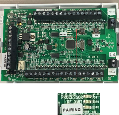
Processor LED (red color): The Processor LED flashes to indicate processor operation.
RF XMIT LED (green color): The RF XMIT LED illuminates when RF transmission is sent.
Pairing LED (red color): The Pairing LED illuminates when the HWIM is in “Pairing” mode and is extinguished when the HWIM is in “Normal” mode. If there are no zones paired the Pairing LED flashes.
Note: The Pairing LED must be extinguished (not in “Pairing” mode) when testing sensors.
Figure 2: Zone LEDs


Zone LEDs (red color): During "Normal Operation Mode" each LED remains off until its corresponding zone is opened, then the LED illuminates. When entering "Pairing Mode" each zone LED flashes briefly, after which each zone LED remains off until the zone is learned in. Once learned in, it illuminates until "Pairing Mode" is complete.
DLY LEDs (yellow color): Zones 1 and 2 each have a DLY LED. When a zone’s DLY LED is illuminated yellow, that zone has the 2-minute communication timer delay enabled. When the DLY LED is off, that zone’s communication timer delay is disabled. When the DLY LED flashes, the associated zone has been tripped, and the 2-minute communication timer delay is in effect. All additional triggers from that sensor are ignored for 2 minutes. We recommend using zones 1 and 2 for motion sensors. For more information, see Programming on page 6.
Figure 3: Buttons
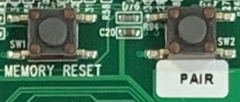
Memory Reset Button: The Memory Reset button clears the HWIM’s memory and returns it to the factory default settings. The Memory Reset button is also used to enable/disable the communication timer delay for Zones 1 and 2.
Pair Button: The Pair button puts the HWIM in/out of “Pairing” mode.
Installation
Only qualified installation technicians should install the HWIM. Clare Controls does not assume responsibility for damages caused by improper installation or use of the device. The HWIM is intended to be mounted to a wall using the included screws and anchors. The HWIM should be oriented with its antennas facing upward. The included antennas should be used regardless of location, for optimal RF communication. Once all sensors are wired to the HWIM, the HWIM and each zone can be paired to the ClareOne panel.
Note: If the HWIM is being installed in a metal container or equipment rack, the antennas must extend outside the container to ensure that the RF communication is not interrupted. Do not bend or alter the antennas
To install the HWIM:
- Carefully select the mounting location, verifying that the HWIM’s antennas are pointing up, and then secure it in position using the provided screws and wall anchors.
Note: The HWIM should be within 1000 ft (304.8 m) of the panel. Walls, construction materials, and other objects may impede the signal and shorten the distance. - Attach each antenna to the HWIM, placing one in each of the ANT terminals on the top of the HWIM.
Note: The antennas should be clear of obstructions and if in a metal enclosure, should extend outside of it. - Wire the sensors/leads to the desired terminals marked Zone 1 through 16.
Wiring Notes:- The HWIM requires 4.7 kΩ of end of line (EOL) resistance on each zone. Existing installations may already have EOL resistors installed. Determine the current EOL resistance value and adjust as needed to get total resistance to 4.7 kΩ.
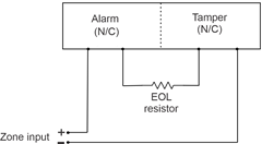
- EOL resistor installation depends on if the sensor is normally open (N/O) or normally closed (N/C). Refer to Determining EOL resistance and sensor type on page 5, for details on determining EOL resistance and if a sensor is N/O or N/C.
- Install one of the included 4.7 kΩ resistors to each zone with an attached sensor. Install the resistor in parallel for N/O and in series with N/C sensors.
- To provide power to powered sensors, such as motion and glass break sensors, wire the Positive and Negative leads from the sensor to the “AUX” (+) and “GND” (-) terminals. See Figure 4 and 5, on page 8.
- Wire the tamper switch input.
Note: This is required for proper device operation.
Option 1: If using a tamper switch, wire the tamper switch directly to the tamper terminals without the need for an EOL resistor.
Option 2: If not using a tamper switch, connect a jumper wire across the tamper input terminals. - (Recommended) For any security system that is supervised, a battery should be connected to the HWIM. To provide an independent battery back up to the HWIM, connect the included battery leads to a 12VDC, 5Ah lead acid rechargeable battery (battery not included). This battery type is common with traditional hardwired security panels, otherwise it is recommended that you connect the HWIM to an auxiliary 16VDC power supply (1 amp or greater) with its own battery backup.
- Connect the power supply leads from the provided power supply to the terminals labeled +16.0V and GND on the wired input HWIM.
Note: The dashed wire is positive. - Plug the power supply into a 120VAC outlet.
Note: Do not plug the HWIM into a receptacle controlled by a switch.
Determining EOL resistance and sensor type
Sometimes, it is not visually apparent what is physically connected to a zone in terms of pre-existing EOL resistors and whether the sensor is N/O or N/C. Use a multimeter to learn this information.
With a sensor in its active state (i.e. door/window contact separated from its magnet), take a multimeter set to measure resistance and connect the multimeter across the zone wires. If the multimeter reads a value of 10 kΩ or less, the sensor is N/O. If the multimeter reads an open or extremely high resistance
(1 MΩ or higher) then the sensor is N/C. The table below provides guidance for using the measurements to determine the EOL resistance value, as well as the line resistance for N/O sensors. This is the case regardless of the number of sensors connected to a single zone, so long as all sensors on the same zone are in series or in parallel with one another.
Note: The HWIM will not work if there is a combination of series and parallel sensors connected to the same input zone.
|
|
Multimeter reads for N/O |
Multimeter reads for N/C |
|
Sensors active |
Value for EOL resistor |
Open |
|
Sensors inactive (Sensors connected to the magnet) |
Value of line resistance (10 Ω or less) |
Value of EOL resistor plus line resistance |
EOL resistance on existing installations typically ranges from 1 kΩ – 10 kΩ while line resistance should be 10 Ω or less. However, some installations do not have any EOL resistors installed and the measured EOL resistance may be the same as the line resistance. If there are no EOL resistors installed, install the provided 4.7 kΩ resistor. Ideally, any existing EOL resistors would be removed and replaced with a 4.7 kΩ resistor. If that is not an option, additional resistors must be added, to get the EOL resistance to 4.7 kΩ.
Programming
There are two portions of programming involved with the HWIM: adding the HWIM to the panel and pairing zones.
Caution: For systems with motion sensors
When pairing a zone, tripping any motion sensor that is not already paired to the ClareOne panel causes the motion sensor to pair in instead of the target zone. This includes pairing in the HWIM. We recommend pairing in motion sensors before pairing in the HWIM or other sensors. This includes wired and wireless motion sensors.
To add the HWIM to the panel:
- Once the HWIM is powered on, open the front cover.
- Press and hold the Pair button on the HWIM for 2 seconds. All zone LEDs flash and extinguish. The Pairing LED illuminates, indicating that the HWIM is in “Pairing” mode.
- Access the ClareOne panel’s Sensor Settings (Settings > Installer Settings > Sensor Management > Add Sensor), and then select "Wired Input Module" as the device type. For detailed programming instructions, refer to the ClareOne Wireless Security and Smart Home Panel User Manual (DOC ID 1871).
- Trip the tamper input, either by opening the tamper switch, or removing the jumper across the inputs. Refer to “To install the WHIM,” step 4, on page 4.
Once complete, close the tamper switch or replace the jumper. - Follow the ClareOne panel on-screen prompts to complete the process.
Note: While a battery backup is recommended, if not adding a battery backup, disable the low battery notifications. To do this, access the HWIM’s sensor settings on the ClareOne panel and set “Low Battery Detection” to Off.
To pair the zones:
Notes
- Each zone must be paired individually, one at a time.
- If using a motion sensor, it is recommended to connect it to Zone 1 or 2, and then enable the communication delay for that zone. If using more than 2 hardwired motions, allocate the most active areas on these zones. The exception would be if using motions in an occupancy detection mode for automation, in which case this setting should not be enabled, or a different zone should be used for that motion sensor.
- Motion sensors should be paired first. This includes both wired and wireless motion sensors.
- If using motion sensors, complete steps 1 through 3 of “To add the HWIM to the panel” on page 6 before continuing.
- Verify that the HWIM’s Pairing LED is illuminated.
If the LED is no longer illuminated, press and hold the Pair button for 2 seconds. - Access the ClareOne panel’s Sensor Settings (Settings > Installer Settings >Sensor Management > Add Sensor), and then select desired zone type as the device type. For detailed programming instructions, refer to the ClareOne Wireless Security and Smart Home Panel User Manual (DOC ID 1871).
- Trip the desired hardwired zone. Once a zone is tripped, its zone LED illuminates and remains lit until the HWIM exits “Pairing” mode.
To enable communication delay for Zone 1 or 2:- Before tripping another sensor press the Memory Reset button.
- The zone’s DLY LED illuminates, signifying that the 2-minute communication timer delay is enabled for that zone.
- Follow the ClareOne panel on-screen prompts to complete the process.
- Repeat steps 2 through 5 for each zone.
- Once all zones are paired, press the Pair button. The Pairing LED extinguishes, signifying the HWIM is no longer in “Pairing” mode.
Note: The HWIM must be taken out of “Pairing” mode before continuing.
Testing
Once the HWIM is installed and programmed with all sensors paired, the system should be tested to verify that the HWIM and zones are working correctly.
To test the HWIM:
- Set the ClareOne panel to “Sensor Test” mode (Settings > Installer Settings > System Test > Sensor Test).
- Trip each zone on the HWIM one at a time. Monitor the system after tripping the zones. Refer to the ClareOne Wireless Security and Smart Home Panel User Manual (DOC ID 1871) for specific test information.
Wiring
The graphic below details the HWIM wiring.
Figure 4: Wiring diagram
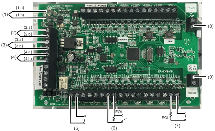
|
(1) 12 VDC Backup battery connection (2) 16 VDC Power supply connection (3) 12VDC Auxiliary Power Output 1 |
(4) 12VDC Auxiliary Power Output 2 (5) Tamper input (6) Wired zone N/O loop (7) Wired zone N/C loop (8) Antenna connection (9) Antenna connection |
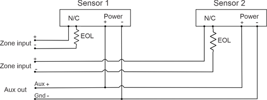
Figure 5: Wiring a powered sensor
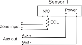
Note: When wiring a sensor that also has a tamper output, the alarm output and tamper output should be wired in series so that the zone triggers on either an alarm or tamper event. See figure below.
Reference information
This section describes several areas of reference information that can be useful when installing, monitoring, and troubleshooting an HWIM.
Status definitions
The ClareOne panel reports the status of the HWIM as Ready by default. Additional HWIM states that may be indicated.
Ready: The HWIM is active and is working properly.
Tampered: The tamper input on the HWIM is open.
Troubled: The HWIM is offline, and nothing has been reported to the panel for 4 hours. At this point, for a monitored system the central station has been informed that the HWIM is offline. Typically, this is either due to power for the HWIM being removed or an object being placed between the panel and the HWIM blocking the RF communication path. Glass, mirrors, and appliances are the most common household items that cause interference.
Low Battery: The low battery indicator is only visible if the Battery Supervision setting is enabled for the HWIM, and the HWIM is either not connected to a battery, or the battery it is connected to is not adequate/low on charge.
Power Loss: When power is removed from the HWIM and there is a battery connected, the HWIM reports a DC power loss. This is indicated on the ClareOne panel as an alert notification. If there is no battery installed, as power starts to go down, the HWIM attempts to send out a power loss event signal to the ClareOne panel; in some instances the power loss event signal is fully received by the ClareOne panel and the alert notification is given.
EOL Resistance
The purpose of EOL resistors is two-fold: 1) to provide an additional layer of security for wired sensors, 2) to check if there is an issue with the wiring going to the sensor.
Without an EOR resistor, someone could short the terminals at the module to make the zone appear to always be closed regardless of activity at the sensor. Since the HWIM requires an EOL resistor, someone cannot short the zone input on the module, as it would cause the module to report the zone in a tampered state. Therefore, it is important for the EOL resistors to be placed as close to the sensor as possible. The further away the EOL resistor from the module, the more wiring can be monitored for unintentional shorts.
Note: If there is a short in the cable between the HWIM and the EOL resistor the HWIM reports the zone as being in a tampered state.
If the wrong value EOL resistor is used or the EOL resistor is installed incorrectly, the zone will not function properly. This can lead to things such as the zone status being reversed (i.e. reporting open when closed and closed when open). It could also lead to the zone reporting a tampered state or being stuck in a Not Ready state to the ClareOne panel.
Multiple sensors on a zone
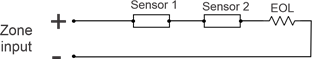
The HWIM allows multiple sensors to be connected on a single zone. For normally closed sensors, the sensors should all be in series with the EOL resistor in series and located at the sensor furthest from the panel. For normally open sensors, the sensors should all be in parallel with the EOL resistor connected across the sensor located at the sensor furthest from the panel.
Figure 6: Multiple N/O sensors on a zone
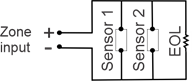
Figure 7: Multiple N/C sensors on a zone
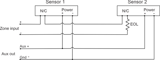
Multiple powered sensors on one zone
For multiple powered sensors on the same zone, the sensors should be wired to the zone as shown in Figures 6 and 7, based on sensors being N/O or N/C. The EOL resistor should be placed at the sensor furthest away from the panel. The power wiring should be run to one sensor and then a second run of wiring should go from the first sensor to the second. Alternatively, the power wiring could go directly from each sensor back to the panel; this requires longer cable runs.
Note: The power connections should be in parallel for each sensor.
Figure 8: Multiple powered sensors on one zone
Multiple powered sensors on multiple zones
For multiple powered sensors on different zones, the sensors should be wired to the zones independently. The power wiring should go directly from the AUX output on the panel to each sensor.
Figure 9: Multiple powered sensors on different zones
Troubleshooting
There is a simple sequence of steps that can be taken to troubleshoot most issues that might arise when using the HWIM. The first step before proceeding with troubleshooting is to make sure that the issue is not network related. It is best to troubleshoot the HWIM using the ClareOne panel and not through the ClareHome application, ClareOne Auxiliary Touchpad, or FusionPro.
- Check status of the HWIM and wired sensors on the ClareOne panel.
- Check for alert notifications on the ClareOne panel, such as DC power loss for the HWIM.
- The HWIM and its wired sensors will continue to report as Ready for 4 hours after losing the RF communication to the panel. A sensor and the HWIM may appear to be in a Ready state, but not appear to be generating events on the panel if there is no power at the HWIM or there is something blocking the RF transmission.
- Check status of the LEDs on the HWIM.
- If the HWIM’s Processor LED is not flashing red, then the HWIM is not functioning properly. It may have insufficient power, or the LED is broken. Check that the power supply is properly connected and that there is 16VDC on the power input terminals on the HWIM. Power cycling the HWIM may help.
- The sensors will not report properly if the HWIM is still in “Pairing” mode, indicated by the Pairing LED being illuminated red. In this case some sensors may report being in a tampered state instead of a Ready state. Pressing the Pair button will end the “Pairing” mode and return the HWIM to “Normal” mode.
- If a Zone LED is flashing red, that indicates that the zone is in a tampered state. Check the wiring on the zone to make sure everything is connected properly, the EOL resistor is properly installed, and is
7 kW. Check to make sure there is not an inadvertent short between the wires. - If a Zone LED does not change state when the sensor is triggered, then there may be an issue with either the wiring to the sensor, power to the sensor, or the sensor itself.
- For powered sensors, verify that the voltage input on the sensor is measured to be within specification for the sensor. If there is a significantly long cable run, the voltage may have a significant drop. This can happen if too many powered sensors are sharing the auxiliary output power causing insufficient current to power the sensor.
Some powered sensors have a LED to indicate that the sensor is working properly. If the LED on the sensor is functioning when the sensor is triggered, then check the wiring from the HWIM to the sensor. - For unpowered sensors, check the wiring from the HWIM to the sensor, including verifying that the EOL resistor is the correct value (4.7 kW) and connected properly. Replacing an unpowered sensor with another sensor can help eliminate a fault in the sensor itself. Take the wires from a known working zone and connect them to the zone of the “bad” sensor. Does the known good sensor continue working? If this is true, then there is an issue with the wiring on the "bad" zone.
- For powered sensors, verify that the voltage input on the sensor is measured to be within specification for the sensor. If there is a significantly long cable run, the voltage may have a significant drop. This can happen if too many powered sensors are sharing the auxiliary output power causing insufficient current to power the sensor.
- If using the communication delay on Zone 1 or 2, the DLY LED is illuminated yellow for the appropriate zone. If the DLY LED is not illuminated, then the communication delay is not enabled. This could lead to multiple events being received by the panel when only one event is expected, or for long delays for other events from being reported.
To enable the communication delay after a sensor is paired:- Enter “Pairing” mode by pressing the Pair button.
- Trigger the sensor on the desired zone.
- Before triggering any other sensor press the Memory Reset button.
Once this is done the DLY LED turn on. Be sure to press the Pair button again to exit "Pairing" mode.
- If using Zone 1 or 2 and the DLY LED is illuminated, the zone will not report open events for 2 minutes after the first event is reported. If this feature is not desired, then the feature should be disabled.
To disable the communication delay:- Enter “Pairing” mode by pressing the Pair button.
- Trigger the sensor on the desired zone.
- Before triggering any other sensors press the Memory Reset button.
Once this is done the DLY LED extinguishes. Be sure to press the Pair button again to exit “Pairing” mode.
- Check wiring to and from the HWIM.
- If the power is not connected properly the HWIM will not work. Make sure that the connections are correct and that the supply is plugged into a non-switch controlled active outlet. Use a voltmeter to measure and ensure input voltage to the HWIM is 16VDC.
- If there is a battery connected make sure the terminals are connected properly (positive terminal on the battery to positive terminal on the HWIM, and negative terminal on the battery to negative terminal on the HWIM). While the wiring is color coded (red for positive and black for negative) it is best to double check that the connections are correct. The battery should measure at least 12VDC when it is not connected to the HWIM. If this is not the case replace the battery with a new one.
- If a sensor is not operating properly check the wiring.
- Check the RF communication.
If everything appears to look good, but events are not being reported consistently/at all to the ClareOne panel, there may be an issue with the RF communication.
-
- Verify there are no obvious impediments to the RF communication path, such as large mirrors or other large objects that may not have been in place when the HWIM was initially installed.
- If the HWIM is installed inside of a metal enclosure, verify the antennas extend outside of the enclosure. Verify that the antennas are not bent or altered.
- Check that the antennas are properly installed, and the screws are tightened.
- If possible, move the ClareOne panel next to the HWIM and trigger a sensor several times. This helps determine if there is an issue with the RF communication due to either impediments in the path or distance between the panel and the HWIM.
Note: If moving the ClareOne panel next to the HWIM for testing, ensure that the ClareOne is connected to local power, ensuring proper testing results.