Description
The ClareOne Glass Break Detector CLR-C1-GB is a wireless glass break sensor featuring alarm, tamper, and low battery signal outputs.
Important safety instructions
Before you install this sensor, be sure to:
- Read, keep, and follow all instructions.
- When there is a low battery, replace with compatible CR123A lithium ion batteries.
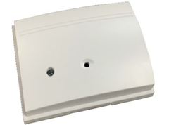
Figure 1: Glass break sensor exterior
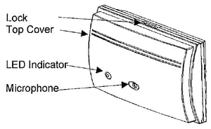
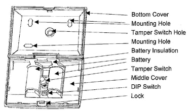
Figure 2: Glass break sensor interior
Installation
Before installing the sensor, we recommend testing, pairing, and setting the sensor’s sensitivity.
Testing the sensor
Test the sensor before placing it in the permanent location.
To test the module/zones:
- Remove the insulation tabs from the battery holder.
Once the tabs are removed and the sensor powers on, Test Mode is active for 5 minutes.
The LED blinks every second while the sensor is in Test Mode. - After 5 minutes, the sensor exits Test Mode and returns to Normal Mode.
Programming
The following instructions step through pairing the sensor to the ClareOne panel.
To add the sensor to the panel:
- Ensure sensor is not faulted.
- Put the ClareOne panel into sensor pairing mode. For detailed programming instructions, refer to the ClareOne Wireless Security and Smart Home Panel User Manual (DOC ID 1871).
- Tamper the sensor.
- Follow the ClareOne panel’s on-screen prompts to name the sensor and make any desired changes to its default settings.
Glass break sensitivity
The sensors sensitivity range can be adjusted by selecting the DIP switch positions.
Set the sensitivity based on the desired range in order to prevent unintentional activations from other sources.
Figure 3: DIP switch
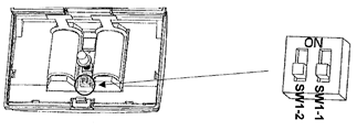
Table 1: Detection range
|
Sensitivity |
Range |
SW 1-1 |
SW 1-2 |
|
Lowest |
4.92 ft (1.5m) |
On |
On |
|
Low |
8.20 ft (2.5m) |
On |
Off |
|
Medium |
13.12 ft (4m) |
Off |
On |
|
Maximum |
19.68 ft (6m) |
Off |
Off |
To adjust the range DIP switches:
- Gently press down on the lock, and then swing the top cover out and away from the bottom cover.
- Slide the SW 1-1 switch to the desired position.
- Slide the SW 1-2 switch to the desired position.
- Swing the top cover back into position, making sure it engages the lock.
Installation
Once the sensor is tested, paired, and its range is set, mount the sensor.
Figure 4: Sensor mounting
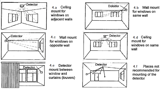
Notes
- It is recommended that the unit be mounted at a height of at least 6.5 ft (1.98m), see fig. 4.
- When the unit is installed in vicinity with active ultrasonic sensors, the distance between units must be at least 4 ft (1.2m).
- All areas of glass to be monitored shall be within a clear line of sight of the unit. Distance from the unit to the most remote point of monitored glass shall not exceed 20 ft (6.05m).
To install the sensor:
- Open the sensor by pressing on the lock and swinging the top cover away from the bottom cover.
- Place the sensor in the desired location and mount the sensor using the supplied screws or 3M tape.
- Mount the magnet into the desired location using the supplied screw and lock washer, making sure the alignment mark lines up with the sensor mark.
Sensor LED
The following section details the sensor’s LED state.
Table 2: LED conditions
|
Condition |
LED state |
|
Power up |
Flash 3 times, once per second |
|
Test Mode/event detected |
Flash once per second (slow) |
|
Test Mode/alarm |
Flash 2 seconds (quick) |
|
Working/alarm |
On for 5 seconds |
|
Low battery |
Flash once every 30 seconds |
Specifications
|
Compatible panel |
ClareOne (CLR-C1-PNL1) |
|
Transmitter frequency |
433 MHz |
|
Encrypted |
Yes |
|
Transmitted indications |
Alarm, tamper, low battery |
|
Supervisory |
60-70 minutes |
|
Max detection range |
20 ft (6.09m) |
|
Min detection range |
5 ft (1.5m) |
|
Glass thickness |
Plate glass at 3mm thickness |
|
Microphone |
Omni-directional with 360° coverage pattern |
|
Battery type |
(2x) 3 VDC Lithium Battery, CR123A |
|
Battery life |
Up to 8 years |
|
Operating environment |
|
|
Storage temperature |
-30 to 140° F (-34 to 60° C) |
|
Dimensions |
3.9 × 2.75 × 1.5 in. |
|
Certification |
FCC: 2ABBZ-RF-GBA-433 |
|
ETL, ETLC |
Pending |