Introduction
Omnistat2 RC-2000 thermostats are programmable communicating thermostats that provide precise digital temperature and humidity control over your HVAC system.
Connect the RC-2000 thermostat to a ClareHome control system so that your customers can send commands to the thermostat to change modes, cool and heat settings, fan status, and other items, from their mobile devices like iPhones or iPads. To adjust temperature and humidity settings, they can simply turn the scroll wheel to the right or left on their ClareHome display. Swipe the screen left and right to switch between the temperature and humidity displays.
The RC-2000 integrates with the ClareHome system in a way similar to the existing HVAC integrations. All HVAC integrations share a common UI, so that the user experience is consistent.
Temperature and humidity settings may be controlled via events, such as the setting of the alarm system. Use Fusion’s Scenes and Rules to automate the actions your customers want.
The following figures show the RC-2000 controls in the ClareHome App.
Figure 1: Temperature mode showing temperature set points
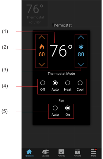
(1) Temperature setting displays on the ClareHome UI in Fahrenheit.
(2) Change the Heat set point by tapping the up/down arrow.
(3) Change the Cool set point by tapping the up/down arrow.
(4) Change the Operation mode by tapping the desired radio button.
(5) Change the Fan mode by tapping the desired radio button.
Set points and the Humidistat mode
The RC-2000 supports two set points for humidity, the humidify set point and the dehumidify set point. These set points are configured through the RC-2000 control panel. However, while the ClareHome system handles both set points, it only displays the humidify set point on its UI display. When a user changes the humidify set point on the ClareHome UI, the delta for this change is also applied to the dehumidify set point.
Example
A thermostat is configured at the RC-2000 control panel with humidify and dehumidify set points of 40 and 70. The ClareHome UI displays the humidify set point value of 40 on the dial. When the user changes this value to 42 on the ClareHome UI, then the dehumidify set point automatically changes to 72.
In this example there is a 30 point difference between the humidify set point (42) and the dehumidify set point (72). As the user adjust the humidify setting up and down, the system maintains this 30 point delta. However, if the user adjusts the humidify set point to 75, then the dehumidify set point will adjust to 100, the maximum setting for dehumidify. The point difference between the two is now 25. This becomes the new delta. So, should the user then adjusts the humidify set point back to 40, the humidify set point automatically adjusts to 65, the 25 point difference of the new delta. To reset the delta to its original 30 point difference, or to change it to a new point difference, the user must return to the RC-2000 control panel and reconfigure it there. The ClareHome UI will then pick up and use the new delta.
Note: The RC-2000 device does not support the Humidistat mode slide display that appears on the ClareHome UI below the humidify dial. In addition, it will always show Enabled. Should the user switch it off, the driver will automatically set it back to Enabled. The UI updates automatically when this occurs.
Connecting the RC-2000 thermostat to the ClareHome data network
Once the RC-2000 is installed, connect it to the ClareHome data network. To make the connection, you will need to attach an IP-to-Serial bridge device to the RC-2000 thermostat and to the ClareHome data network. In addition, you will also need to install a DB-9 female to RJ-45 adapter between the IP-to-Serial device and the RC-2000 thermostat.
Note: The IP-to-Serial device must be able to operate at 300 baud.
To connect the RC-2000 thermostat to the ClareHome data network:
1. Attach one end of a Cat 5 networking cable to a port on the ClareHome data network, and then attach the other end of the cable to RJ-45 jack on the IP-to-Serial device. See Figure 3.
2. Attach the female end of a DB-9 to RJ-45 adapter to the male end of DB-9 connector on the IP-to-Serial device. See Figures 3 and 4.
3. Plug one end of a Cat 5 cable into the RJ-45 jack on the IP-to-Serial device, and then cut and strip the cable to length and wire it according the directions below. This is a straight-through connection. See Figure 3.
/Image%20002.png)
To wire to the RC-2000 thermostat:
1. Connect pin 4 to the Yellow connector on the Comm. portion of the connectors on the thermostat back housing (DTR). See Figure 5.
2. Connect pin 3 to the Green connector on the Comm. portion of the connectors on the thermostat back housing (TXD).
3. Connect pin 2 to the Black connector on the Comm. portion of the connectors on the thermostat back housing (RXD).
4. Connect pin 5 to the N/C connector on the Comm. portion of the connectors located on the thermostat back housing (GND).
5. To ensure communication via a serial connection, remove the jumper J8, located on the rear, bottom left side of the thermostat.
/Image%20003.png)
Setting the serial parameters in the IP-to-Serial device
To ensure proper communication between the RC-2000 and the ClareHome system, you must configure your IP-to-Serial device with the following settings.
/Image%20004.png)
Note: When setting serial parameters in your IP-to-Serial device, refer to the manufacturer’s instructions.
Configuring in Fusion
After setting up and configuring your RC-2000 device, you must add and configure it in Fusion. Once added, you can use the Service Wizard to add a service for it. The Service Wizard will step you though the process and auto-populate the fields for you. Follow the steps below to add and configure your RC-2000 device in Fusion.
To add an RC-2000 device in Fusion:
- Click the Devices tab, and then click the New Device button to display the Select Template dialog.
/Image%20005.png)
- Expand the Climate folder, and then select HAI - Omnistat 2 RC-2000 - Humidistat from the list.
- In the Details tab’s Name field, enter a name for your RC-2000 device.
/Image%20006.png?width=550&name=Image%20006.png)
- Click the Configuration tab.
/Image%20007.png?width=550&name=Image%20007.png)
- Enter values in the following fields:
- Thermostat ID: 1 or the number thermostat the device is in the home.
- Network Address: The device’s IP address.
- Network Port: Port number for the IP-to-Serial device that connects the RC-2000 module with the ClareHome data network.
Note: Check the documentation that came with the device to determine the proper network port number.
- Click the Save button.
- On the Configure tab, click the New Service Instance button to display the Create Service dialog.
/Image%20008.png)
- In the Service Name field, enter a name for your service. This is the name that appears on the customer’s mobile device – for example, Living Room Thermostat.
- Click Open Wizard to display the Service Instance dialog. Click Thermostat Service, and then click Next.
/Image%20009.png?width=550&name=Image%20009.png)
- Fusion displays the New Service Instance Devices tab and auto-populates the control points for the RC-2000 device.
/Image%20010.png?width=550&name=Image%20010.png)
- Click Finish, and then deploy the project.
Known issues
The following are known issues in this release of Omnistat2 RC-2000.
/Image%20011.png)