Introduction
The Elk M1 Security Panel is tested and certified for integration with the ClareHome system. To integrate the Elk M1 panel, you will need access to the ELKRP configuration tool or a global caché device. The Elk panel must be configured with the settings required by the ClareHome system.
The instructions in this document are provided to help you quickly integrate the panel into the ClareHome system. It lists the settings required by ClareHome for the systems to sync and communicate properly. It is not intended to be a complete installation guide.
Follow the manufacturer’s installation documentation, included with the product, when installing the M1.
Note: When making changes to the M1 panel, the project must be re-deployed for changes to take effect.
Supported features
The following features are supported in the M1.
Controls
The following commands are supported.
Note: The controls set the security panel’s state.
- Arm: This command arms the panel.
- Disarm: This command disarms the panel.
- Arm Away: The panel arms in away mode, activating the entire security system (internal and external).
- Arm Stay: The panel arms in stay mode, turning off the home’s internal motion detectors.
- Bypass Zone: This command allows the user to set the alarm as normal but ignores the alarm in the specified zone(s). When the bypassed zone is tripped, the alarm does not go off. For example, setting your Lanai as a bypass zone allows the pool cleaner to enter and work without triggering the home’s alarm.
- Unbypass Zone: This command removes the bypass setting of the zone.
Feedback
The following states are set in the security panel based on the commands received from the user.
Note: The feedback states can be used in Fusion to create rules and notifications. For example, when the security panel is disarmed by a family member, the welcome scene runs, turning on all lights and sending a notification to the homeowner that a specific family member has disarmed the system.
- Partition status: The system is either faulted, or ready.
- Fire alarm: The system’s connection to the fire alarm.
- Ready to arm: The system is ready to arm.
- Arming: The security system is now arming.
- Zone status: The real-time status of the zone – ready, faulted, bypassed, or troubled.
- Armed: The panel is currently in an armed state.
- Armed away: The panel is in the armed away state, fully armed.
- Armed stay: The panel is in the armed stay state, with only the outside motion detectors active.
- Disarmed by: The user who disarmed the panel.
- Armed by: The user who armed the panel.
Installation
A qualified technician should install Elk M1 security panels. Refer to the installation instructions that came with your device. Clare Controls does not assume any responsibility for damages caused by improper installation or connection to the network.
Using a serial connection with the Elk M1
After installing the M1, connect it to the ClareHome data network. To make the connection, you will need to attach a serial adapter, such as a Global Cache’ iTach device or a SENA serial device server. You will also need a null modem cable, or a null modem adapter with a serial cable.
To connect the M1 to the ClareHome data network:
- Attach one end of a null modem cable (with a male DB-9 connector), to the serial connector on M1 panel, and then attach the other end of the cable to the serial adapter device (Global Cache’, SENA, or other).
- Attach one end of a Cat 5 networking Ethernet cable to the port on the serial adapter device, and then attach the other end of the cable to a port on the ClareHome data network.
- Configure the serial adapter with the port parameter settings in Table 1.
Table 1: Serial adapter settings
|
Serial Parameter |
Setting |
|
Baud Rate |
115,200 |
|
Data Bits |
8 |
|
Parity |
None |
|
Stop Bits |
1 |
Notes
- To configure the serial adapter, follow the manufacturer’s instructions included with the device.
- When using the M1 to communicate with ClareHome, the panel PIN must not end with a zero (0). Zeros are used as padding and are ignored.
Connecting the Elk M1 to the ClareHome project
After installing the panel, connect it to the CLIQ controller. The M1 requires a null connection. When using the M1 with a CLIQ.mini, you must use a USB to serial cable with a null modem adaptor.
To connect the Elk M1 to the CLIQ.mini:
Note: You will need the USB to serial cable (part number CLIQ-SEC-USB-01) and a null model adapter.
- Attach the USB end of the USB to serial cable to a USB port on the CLIQ.mini.
- Attach the opposite end of the USB to serial cable (DB-9 connector) to the null model adapter.
– or –
Move the jumpers on the M1 to support straight through communication. - Attach the opposite side of the null modem adaptor to the serial connector on the M1.
Configuring the Elk M1 for communication with the CLIQ
To ensure that the M1 can communicate with ClareHome, install your panel as instructed in the Elk M1 manufacturer installation guide. Configure the required settings listed below.
To configure the M1:
- Enter *, 8. All of the function key LEDs begin to flash.
- Enter the Go To Program code (default 9713). If the code is valid, the Service LED flashes, and the function LEDs illuminate steadily, indicating you should enter the device to program.
- Enter 0, 0, ..., the address of the M1. The Armed LED illuminates until you enter a programming location.
- Enter the programming location followed by the ... key. The Armed LED begins to flash. If this is a valid location, the Armed LED extinguishes, the Ready LED illuminates, and the binary data for the first segment of this location appears on the Zone LED.
- To change the data, enter data followed by the * key. The location automatically increments to the next segment. The data for that segment displays. Repeat the procedure until the system reaches the last segment.
- Set the locations with the data as follows:
Table 2: M1 required settings
|
Required settings |
Location |
Segment |
Enabled bits |
|
Feature report selection/partition feature selection |
23 |
1 |
1---5--- |
|
23 |
2 |
---4---- |
|
|
23 |
3 |
-----678 |
|
|
23 |
4 |
-------- |
|
|
23 |
5 |
Reserved |
|
|
Serial port selector |
207 |
1 |
|
|
Baud rate (115,200) |
208 |
2 |
|
|
Home automation protocol |
209 |
1 |
|
|
Transition based broadcasts |
210 |
1 |
-2--5-7- |
|
210 |
2 |
1------- |
|
|
Command/request enables |
211 |
1 |
-2-45678 |
|
211 |
2 |
12345--- |
|
|
211 |
3 |
12345678 |
|
|
211 |
4 |
--345678 |
|
|
LCD keypad address |
212 |
192 |
Note: When setting the panel PIN in the M1, do not end the PIN with zeros (0). Zeros are used as padding and are ignored.
Configuring the panel with ElkRP
Configure the M1 panel using the ElkRP Windows programming tool.
To configure the panel using the ElkRP programming tool:
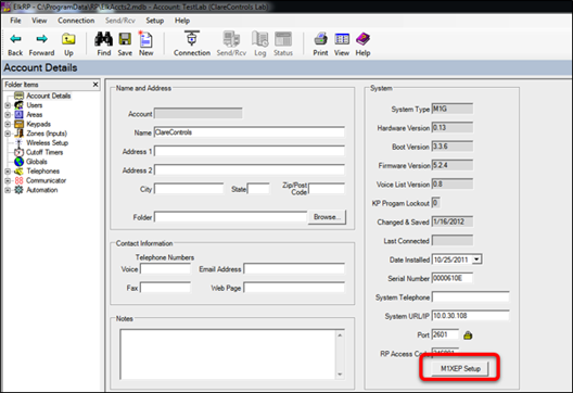
- Launch the ElkRP programming tool.
- Click M1XEP Setup.
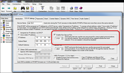
- Click the TCP/IP Settings tab, select the Enable Non-Secure Port checkbox, and then in the field enter the port number 2101.
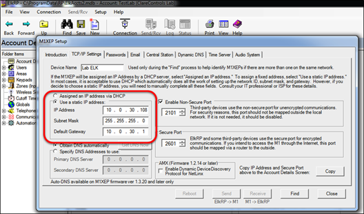
- Select Use a static IP address, and then configure the static IP address information.
- Then add and configure the Elk M1 in Fusion.
Configuring in Fusion
Once configured, add and configure the Elk M1 in Fusion. This includes defining partitions and zones created when configuring the Elk M1, and then creating a service for each partition. Follow the steps below to configure your security system in Fusion.
Creating a partition
Begin by creating the partitions. Be sure that you create a partition for each partition you defined in your M1.
To add the M1 in Fusion:
- Click the Devices tab, and then click the New Device button
 to display the Select Template dialog.
 - Browse to Elk - Security - M1 Gold Series.
Security > Security Systems > Elk - Security - M1 Gold Series - Select CLIQ in the Communication Method drop-down if you are using a CLIQ.host or a CLIQ.mini.

– Or –
Select Other in the Communication Method drop-down if you are using serial.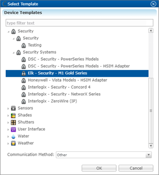
- Click OK.
- The security Device Wizard displays. Select the number of zones, and then click OK.
Notes
- One partition is created automatically. Additional partitions must be added manually.
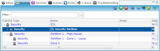
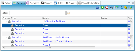
- The number of zones you enter must match the number of zones defined in the M1 panel. In the example below, we create three zones.

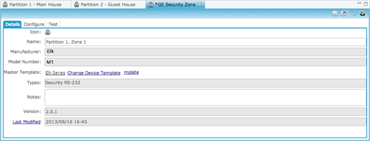
- The Details tab displays.
Enter a name for your Elk M1.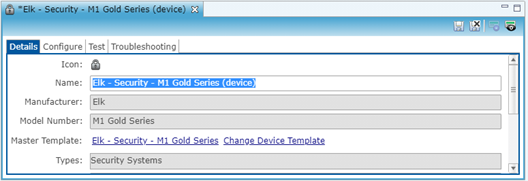
- Click the Configure
- Configure the fields with the serial information.
Note: Ensure that you select the proper value for the CLIQ Serial Port drop-down. CLIQ.host and CLIQ.mini each have port options.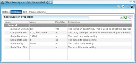
– Or –
Configure the fields with the correct IP information.
Note: The Network Address and Network Port are unique to your system.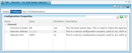
- Click the Save button
 .
.
To configure a partition:
- Return to the Devices tab, and then double-click the first partition to display its Details tab.
- Enter a name for the partition.
In our example below, the first partition is named “Partition 1, Main House.”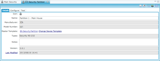
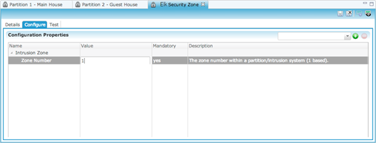
- Click the Configure
- In the Value field, enter the partition number.
- Click the Save button
 .
.
To manually add partitions to the security system:
Note: When adding partitions, be sure that you do not duplicate the partition numbers. Each partition number must be unique.
- Return to the Devices tab.
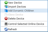
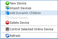
- Right-click the partition, and then select Add Dynamic Children.
- The security Device Wizard displays.
- Select the number of partitions, and then click OK.
- Return to the Devices tab and browse to the first security partition to configure.
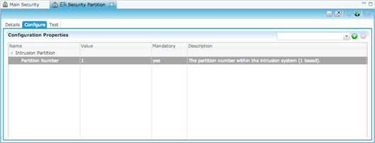
- The Details tab displays. Enter a name and notes for the device if desired, and then click the Configure tab.
- Expand the Intrusion Partition drop-down, and then enter the partition number in the Value field.
- Click the Save button
 .
. - Repeat steps 1 through 8 for each partition.
To manually add zones to a partition:
- Return to the Devices tab.
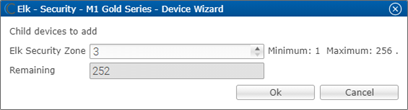
- Right-click the first partition, and then select Add Dynamic Children.
- Fusion has added the first zone for you. Enter the number of additional zones for this partition.

- Click OK.
- Return to the Devices tab, and then browse to the first security zone to configure.
- Fusion displays the Details tab for the first zone. Name the zone.
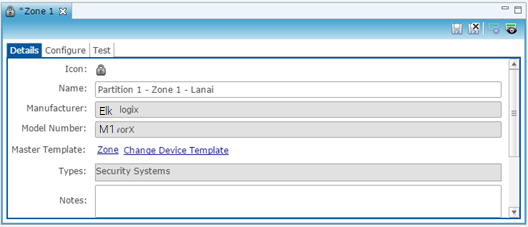
- Click the Configure tab, and enter the zone number in the Value field.
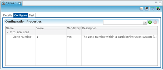
- Click the Save button
 .
. - Repeat steps 1 through 4 for each partition, and 5 through 8 for each zone.
To create a service for a partition:
- Click the first partition in the list to display its Details tab, and then click the New Service Instance button
 to display the Create Service dialog.
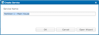
- Click Open Wizard to display the Service Instance dialog, select Intrusion Partition Service, and then click Next.
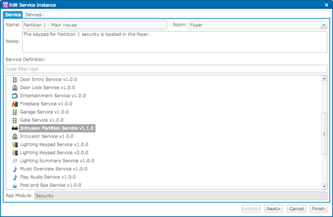
- Fusion displays a checkmark for the selected partition and its zones. If not, select the partition and zones on the left side of the window.
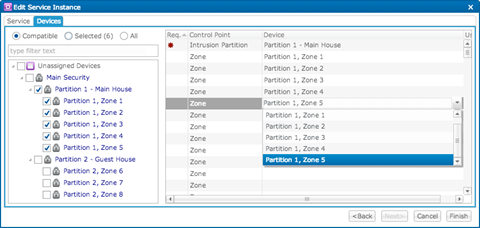
- Set the control points for the partition and zones.
On the right side of the window, click inside the Devices field, and then select a zone from the dropdown list. - Click Finish, and then deploy your project.
Configuring rules with the M1
The following example sets an Armed-Away rule. When the M1 is set to Arm-Away, the Goodbye – Lights Off scene runs.
To create an Armed-Away mode rule in Fusion:
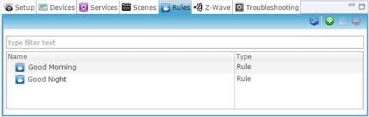
- Access your project, and then click the Rules tab.
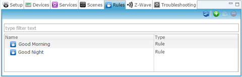
- Click the New Rule button
 .
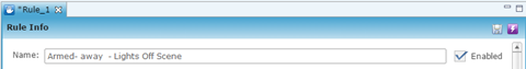
. - Enter a name for the rule, and then select the Enable Rule checkbox.
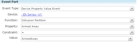
- Configure the Event Part as below.
- Event Type: Device Property Change Event
- Device: Elk Series – M1
- Function: Intrusion Partition
- Property: Arm Away
- Constraint: =
- Value: ArmedAway
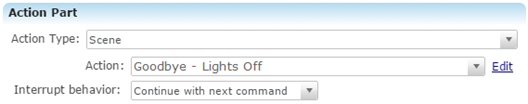
- Configure the Action part as below.
- Action Type: Scene
- Action: Goodbye – Lights Off
- Interrupt behavior: Continue with next command
- Click the Save button
 , and then deploy the project.
To create a disarmed by rule in Fusion:
Note: The Elk panel must be configured with individual pin numbers assigned to people with access to the property. If the Elk panel is not configured with individual pin numbers, this rule will not work properly. To set pin numbers in the Elk see the documentation that came with the device.
- Access your project, and then click the Rules tab.
- Click the New Rule button
 .
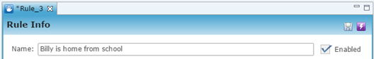
. - Enter a name for the rule, and then select the Enable Rule checkbox.
- Configure the Event Part as below.
- Event Type: Device Property Change Event
- Device: - Elk
- Function: Intrusion Partition
- Property: Disarmed By
- Constraint: =
- Value: Billy
Note: The Value field must be identical to the name configured in the Elk panel.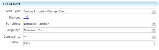
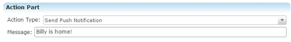
- Configure the Action Part as below.
- Action Type: Send Push Notification
- Message: Billy is home!
- Click the Save button
 , and then deploy the project.
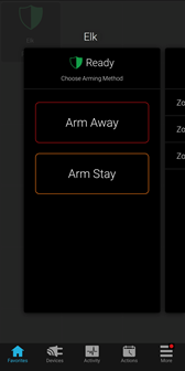
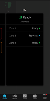
User Interface
The following figures show the Elk controls in the ClareHome app.
Figure 1: Elk Security System UI in ClareHome
Full PDF - Elk Security Integration Release Notes (DOC ID 1988)