Introduction
The Clare Security panel is an IP security panel and alarm system created for residential use. It has been tested and certified for integration with ClareHome.
The instructions in this document help you quickly integrate the panel into the ClareHome system and configure ClareNet Activation. This document is not intended to be a complete installation guide.
Notes
- The security panel supports one partition.
- Only 1 panel can be integrated with a ClareHome project.
- The security panel’s initial configuration must be done with the Clare Controls Install Assist App.
Supported models
CS-SEC-10
Clare Security Panel supported properties in ClareHome
The following panel features are supported in ClareHome.
- Arm and disarm: Arm and disarm are options in the user interface. Swipe the screen to arm or disarm the system.
- Armed stay: The panel arms in stay mode, bypassing zones that are not included in arm stay (motion detectors) by default, each zone is configurable.
- Armed away: The panel arms in away mode, activating the entire security system (internal and external).
- Zone status: The user can see the status of all zones in the system.
- Zone bypass: Bypasses a zone the next time it is armed. Zone bypassing is only available when the panel is unarmed.
- Zone configuration: Configure zone properties.
- Zone pair/remove: Pair and remove zones through the Install Assist App.
- Security settings: Configure all settings through the Install Assist App.
- User PINs: Configure user PIN numbers through Fusion.
Installation
A qualified technician should install the security panel. Refer to the installation instructions that came with your device. Clare Controls does not assume any responsibility for damages caused by improper installation or connection to the network.
Note: You need 2 Ethernet cables and an Ethernet switch.
Installation with Wi-Fi in the Home
The CLIQ.mini and panel can be configured with the home’s existing Wi-Fi.
To connect the panel to the CLIQ:
Note: This scenario requires the CLIQ device to use the home’s existing Wi-Fi network.
- Connect the panel’s power supply to the power port on the panel.
- Connect an Ethernet cable to the CLIQ, and then connect the other end of the cable to an Ethernet switch.
- Connect a second Ethernet cable to the switch, and then connect the other end of the cable to the security panel.
- Connect your iOS device or Android smartphone to the home’s Wi-Fi network.
Note: This requires the home’s Wi-Fi SSID and password. - Configure and setup the panel using the Clare Controls Install Assist App.
Note: When setting up the panel, use Install Assist to configure the panel and devices. If the panel and devices are not configured through Install Assist, the devices do not integrate correctly.
Installation without Wi-Fi in a home
To connect and configure the panel in a home with no Wi-Fi, the CLIQ.mini must be in AP mode with no router attachment.
Notes
- You will need 2 Ethernet cables and an Ethernet switch.
- PoE switches are not supported for this installation method. The PoE injector, included with the CLIQ.mini, can be used. Do not use the LAN port until the device is ready to connect to the internet.
- A router is not used in this setup, you must use an Ethernet switch.
To connect the panel to a CLIQ.mini using AP mode:
- Attach the power supply to the power port on the panel.
- Connect an Ethernet cable to the panel, and then connect the other end of the cable to an Ethernet switch.
- Attach the CLIQ.mini to its power supply, and then wait for the mini to power on.
- Verify that the CLIQ.mini is in AP mode, the LED flashes red in .5 second intervals. If it is not, see “To reboot the CLIQ.mini and enter AP mode,” on page 4.
- Attach a separate Ethernet cable to the CLIQ.mini, and then plug the other end of the cable into Ethernet switch. Wait for the CLIQ.mini to broadcast its Wi-Fi, and then connect your iOS device or Android smartphone to the mini’s Wi-Fi.
See “To connect to the CLIQ.mini’s Wi-Fi using an iOS device."
– or –
See “To connect to the CLIQ.mini’s Wi-Fi using an Android device.” - Use the Install Assist App to configure the panel and devices, see “Configuring with Clare Controls Install Assist.”
Note: If the panel and devices are not configured through Install Assist, the devices do not integrate correctly. - After Configuring the panel using the Install Assist App, remove the Ethernet switch, and when available, connect the CLIQ.mini to the home’s Wi-Fi. See “Connecting the CLIQ.mini to Wi-Fi from AP mode.”
To reboot the CLIQ.mini and enter AP mode:
- Locate the recessed push button on the CLIQ.mini.
/Clare%20Secure%20001.png?width=336&name=Clare%20Secure%20001.png)
- Insert the paper clip (provided), pressing the button down and holding for 20 seconds.
/Clare%20Secure%20002.png?width=210&name=Clare%20Secure%20002.png)
- Remove the paper clip and observe the LED behavior.
The CLIQ.mini’s LED indicators alternate red and blue signifying it has entered the reboot state. - Once the CLIQ.mini boots and the LED flashes red in .5 second intervals, it is in AP mode. Connect your Android or iOS device to the mini’s Wi-Fi and continue using the Install Assist App.
To connect your CLIQ.mini with LAN from AP mode:
- Verify that your mini is in AP mode (LED flashes red in .5 second intervals.)
- Connect the Ethernet cable to the Ethernet port on the CLQ.mini. See Figure 1, item 6.
- Locate the recessed push button on the CLIQ.mini. See Figure 1, item 1.
- Insert the paper clip (provided) pressing the button down and holding for 5 seconds.
- Remove the paper clip and observe the LED behavior. The CLIQ.mini’s LED indicators alternate red and blue signifying it has started shutting down.
- After the CLIQ.mini shuts down, disconnect the CLIQ.mini’s power supply.
- Reconnect the power supply and verify that the CLIQ.mini restarts. Continue with installation and setup.
Figure 1: CLIQ.mini rear connections
/Clare%20Secure%20003.png?width=336&name=Clare%20Secure%20003.png)
|
(1) Recessed push button (2) 2 USB ports (3) Wire routing channel |
(4) Wall mount slots (5) Micros USB port (6) Ethernet port |
To connect to the CLIQ.mini’s Wi-Fi using an iOS device:
Note: To use this App successfully you must be connected to the CLIQ.mini’s Wi-Fi. This Wi-Fi network displays as ClareWifi-xxxx. The xxxx is replaced with the last 4 digits of your CLIQ.mini’s MAC address.
- Tap Settings.
- Tap Wi-Fi, and then select the CLIQ.mini’s broadcasted Wi-Fi.
/Clare%20Secure%20004.png?width=250&name=Clare%20Secure%20004.png)
- Return to the home screen and tap the Install Assist icon to access your App.
To connect to the CLIQ.mini’s Wi-Fi using an Android device:
- Access the device’s settings.
- Tap Wi-Fi, and then select the CLIQ.mini’s broadcasted Wi-Fi.
/Clare%20Secure%20005.png?width=250&name=Clare%20Secure%20005.png)
- Return to the home screen and tap to access your App.
Note: Some Android phones require Wi-Fi verification if there is no internet access. Opt to allow the Android device to stay connected to the CLIQ.mini’s Wi-Fi. For more information and detailed instructions, see CLIQ.mini and Android Nougat: AP Mode Wi-Fi Error (DOC ID 1459).
Connecting the CLIQ.mini to Wi-Fi from AP mode
After using the Install Assist App in AP mode, the CLIQ.mini remains in AP mode. Leave the mini in this state until internet is available to the home. Once Wi-Fi is available, use the Install Assist App to configure the CLIQ.mini to the home’s Wi-Fi network.
To connect the CLIQ.mini to the home’s Wi-Fi network using Install Assist:
- Launch the Install Assist App.
/Clare%20Secure%20006.png?width=250&name=Clare%20Secure%20006.png)
- Tap WiFi Config.
Note: If you are using an Android smartphone, tapping in the WiFi network SSID field presents the user with a Wi-Fi drop-down menu. Select the appropriate network./Clare%20Secure%20007.png?width=250&name=Clare%20Secure%20007.png)
- Enter or select (if using an Android smartphone) the Wi-Fi network SSID, the password, confirm the password, and then tap Next.
/Clare%20Secure%20008.png?width=250&name=Clare%20Secure%20008.png)
- Read the displayed information and then tap Yes or No
If tapping Yes, continue the configuration steps./Clare%20Secure%20009.png?width=250&name=Clare%20Secure%20009.png)
– or –
If you tapped No, onscreen status LEDs and instructions display. You must verify the network is available and the CLIQ.mini is set in AP mode, and then return to step 1./Clare%20Secure%20010.png?width=250&name=Clare%20Secure%20010.png)
- Tap Go to Settings, and then verify that your iOS device or Android smartphone is connected to the correct Wi-Fi network.
Configuring with Clare Controls Install Assist
After the panel is successfully installed, add and configure it with the Install Assist App.
To add devices with the App:
- Tap Add Devices.
- At the bottom of the screen, tap the plus icon.
/Clare%20Secure%20011.png?width=250&name=Clare%20Secure%20011.png)
- Tap Security.
/Clare%20Secure%20012.png?width=250&name=Clare%20Secure%20012.png)
- Read the displayed information, and then tap Discover the security panel.
/Clare%20Secure%20013.png?width=250&name=Clare%20Secure%20013.png)
- The panel is discovered. Enter a name for the panel, and then customize the panel settings as desired.
Notes
- Discovery can take up to a minute.
- The panel’s defaults are recommended for standard use.
/Clare%20Secure%20014.png?width=250&name=Clare%20Secure%20014.png)
System Settings
Audible Alarm: This feature allows audible alarms. If disabled all audible alarms, except chimes, are silenced.
Global Auto Bypass: This allows a zone(s) to be bypassed when the alarm is set. It must be enabled for the auto bypass to function.
Global Chime: This allows the panel to use chimes. If this is not enabled, all chimes are silenced.
Delay options
Note: There are 2 delay options, allowing zones to use different set delays.
Long Entry Delay: The time in seconds between a zone fault (door opening) and triggering the alarm. This is set to a longer amount of time than the Standard Entry Delay.
Standard Entry Delay: The time in seconds between a zone fault (door opening) and triggering the alarm. This is set to a shorter amount of time than the Long Entry Delay.
Status (Chime/Arm/Disarm) Volume: This determines the volume of chimes and entry/exit delays sounds.
Wireless Siren Status Volume: This determines the volume for any wireless sirens used with panel.
- Tap < Edit Device to save the panel settings.
The security devices page displays./Clare%20Secure%20015.png?width=250&name=Clare%20Secure%20015.png)
- Tap the plus icon to add a new security zone (sensors, keypads, and sirens).
/Clare%20Secure%20016.png?width=250&name=Clare%20Secure%20016.png)
- Tap Pairing Process, and then follow the on-screen instructions regarding device tab removal.
Note: The Advanced option is only used for the hardwired zone input module.
-
The security zone is discovered, name the zone and custom the desired fields.
/Clare%20Secure%20017.png?width=250&name=Clare%20Secure%20017.png)
Device Settings
Clare Controls currently supports Clare Security peripherals and sensors. Each sensor has configurable settings. See below for a list of supported peripherals/sensors and the configurable sensor settings.
Note: Peripheral devices, such as the sirens, keypads, and key fob do not have configurable settings are not displayed in the ClareHome or Install Assist App.
Supported sensors and peripherals
CS-DWS-10 Window/Door Sensor
CS-PNC-10 Panic Pendant
CS-GBS-10 Glass Break Sensor
CS-SMK-10 Smoke Detector
CS-CMD-10 Carbon Monoxide Detector
CS-SRN-10 Siren with Battery Backup
CS-WRP-10 Wireless Range Extender
CS-PIN-10 Wireless Pinpad
CS-OMS-10 Outdoor Motion Sensor
CS-360-10 360 Degree Ceiling Mount Indoor Motion Detector
CS-KFB-10 5-Button Security Keyfob
CS-WTR-10 Water/Temp Sensor
CS-PIR-10 PET Immune PIR Motion Sensor
CS-NDWS-10 Micro Window/Door Sensor
CS-MMA-10 Micro Mounting Accessory
CS-HWT-10 Hardwired Zone Input Module
Configurable sensor settings
Active in Arm Away: This enables/disables the zone generation of an alarm event while in Arm Away mode.
Active in Arm Stay: This enables/disables the zone generation of an alarm event while in Arm Stay mode.
Allow Bypass: This enables/disables the ability to bypass the zone.
Auto Bypass: This enables/disables the zone to be automatically bypassed if it is open when arming the panel.
Close Chime: This turns on/off the audible chime when the zone is closed.
Entry/Exit Delay: The entry/exit delay setting for arming and disarming, select Long, Short, and Standard. Exact values are configured in partition.
Follow Zone: This enables/disables the application of the entry/exit delay.
Open Chime: This turns on/off the audible chime when a zone is opened.
Report Code: The intrusion perimeter set for an input.
Sensor Input Name: The configured external input number.
- Repeat steps 6 through 9 for each zone.
- Connect the CLIQ.mini to the home’s network.
Hardwired zone input module configuration
The hardwired zone input module is used to convert existing wired security sensors to wireless protocol in order to communicate with the ClareSecure panel. Use the Install Assist app to configure the zones after the physical installation is complete.
To configure the module in Install Assist:
Note: Configuration of the wired zones requires that the installer records which sensors are connected to which physical connectors on the module.
- Tap Add Devices.
- At the bottom of the screen, tap the plus icon.
- Tap Security.
- Tap Advanced.
- Enter your zone input module's serial number, and then tap Get Zone Inputs.
/Clare%20Secure%20018.png?width=250&name=Clare%20Secure%20018.png)
The zone inputs display./Clare%20Secure%20019.png?width=250&name=Clare%20Secure%20019.png)
- Using the first configured input on the module, select the zone’s profile.
Note: Configure the zone inputs in order to avoid confusion. There are no names displayed, only zone numbers (zone names can be changed later in the process). The configured inputs may not start with Zone 1 in the security device list. For example, the security panel has 2 motion sensors (zone 1 and 2), the first configured input will be automatically assigned to zone 3, or the next available zone in the configuration. If there is a gap in the zone number, i.e. there are 6 zones and zone 4 is removed, the next zone to be added is zone 4./Clare%20Secure%20020.png?width=250&name=Clare%20Secure%20020.png)
- Once the input is selected, tap Save.
Note: You must tap Save after selecting each input./Clare%20Secure%20021.png?width=250&name=Clare%20Secure%20021.png)
- Repeat steps 6 through 7 for each additional input.
Note: Once an input is saved, it is no longer available to select/edit. To reuse or reconfigure an input, the zone must be deleted and then re-added./Clare%20Secure%20022.png?width=250&name=Clare%20Secure%20022.png)
- After module configuration, tap Go To Security Devices.
/Clare%20Secure%20023.png?width=250&name=Clare%20Secure%20023.png)
All configured security devices display.
Zones created using the hardwired zone input module can be modified or deleted like other security devices.
To check a zone’s input:
- Tap the desired zone.
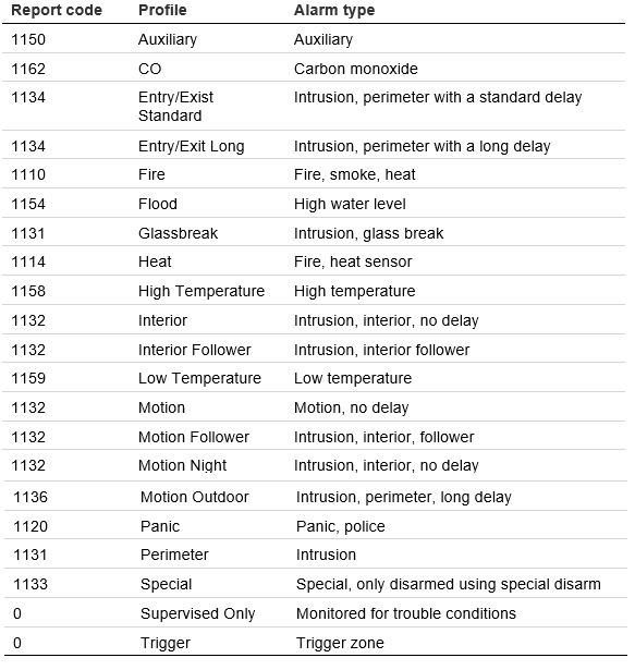
- Scroll down to view the report code and input field.
For report code meaning, see Table 1: Input report codes, profiles, and alarm type./Clare%20Secure%20025.png?width=250&name=Clare%20Secure%20025.png)
Clare Security Panel user management
User management allows the homeowner to change their security system’s PIN, create new users, remove users, and reset existing PINs.
Note: For security, no one can see another user’s PIN. This information is private. If a user forgets their PIN, the homeowner/master user can reset the PIN. If the master user forgets their PIN, the security panel must be factory defaulted and requires configuration assistance from the installer.
To access user management:
- Launch the ClareHome app, and then tap the Menu icon.
- Tap Devices.
- Tap Security, select the security panel.
/Clare%20Secure%20026.png?width=250&name=Clare%20Secure%20026.png)
- Tap Configure Security Users.
/Clare%20Secure%20027.png?width=229&name=Clare%20Secure%20027.png)
- Enter the User PIN, and then tap Submit.
/Clare%20Secure%20028.png?width=250&name=Clare%20Secure%20028.png)
Notes
- The Master User PIN is set by the security dealer when the security system is installed. This PIN should be changed by the homeowner once they are in possession of the security system. This PIN gives the user the ability to manage other users and change their PIN.
- Any user PIN that has access to manage users can be used.
- If you enter the PIN of a user that does not have permission to manage users, you are unable to proceed.
- A list of the panel’s users displays.
To add a new user:
- Tap the blue Plus icon at the bottom.
The New User dialog displays./Clare%20Secure%20030.png?width=250&name=Clare%20Secure%20030.png)
- Enter the User Name, User PIN, and confirm the PIN.
Note: Only select the checkbox if you want the new user to be able to view and modify existing users./Clare%20Secure%20031.png?width=250&name=Clare%20Secure%20031.png)
- Tap Save.
To modify an existing user:
- Tap the desired user’s name.
/Clare%20Secure%20032.png?width=250&name=Clare%20Secure%20032.png)
- Modify the user as desired, and then tap Save.
To remove a user:
- Tap the dots next to the desired user’s name.
- Tap Remove, and then confirm user’s removal.
To modify the Master PIN:
- Tap the master user’s name.
Note: If you change the master user’s PIN, note it. If this PIN is forgotten the security panel must be factory reset./Clare%20Secure%20033.png?width=250&name=Clare%20Secure%20033.png)
- Modify the user as desired, and then tap Save.
Configuring in Fusion
After installation and panel configuration, the device is automatically added to Fusion. Access the partition in Fusion to manage users and configure rules if desired.
Note: The panel supports one partition.
Managing users
Once you have added the panel, add and manage the users.
To access the Intrusion User Admin Menu:
- Access the desired Fusion project and view the devices.
- Expand the security panel to view the partition.
/Clare%20Secure%20034.png?width=550&name=Clare%20Secure%20034.png)
- Double click the partition, the partition’s Details tab displays.
- Click the Test tab, and then expand Intrusion User Admin.
/Clare%20Secure%20035.png?width=550&name=Clare%20Secure%20035.png)
List Users: This button displays a list of all current users and their configured information including PIN, Username, Displays name, and User ID./Clare%20Secure%20036.png?width=550&name=Clare%20Secure%20036.png)
Note: The user id’s start at 0. The default master user id is 0. The first user manually added is user 1.
Create User: This button allows you to create a new user for the security panel.
- Configure the boxes as follows.
IN1: The user’s desired PIN.
IN2: The user’s User Name.
Note: Leave IN3 and IN4 blank. Information entered in these fields is not used.
/Clare%20Secure%20037.png?width=336&name=Clare%20Secure%20037.png)
- Click Execute.
The results box displays. If the operation was successful, the box displays true./Clare%20Secure%20038.png?width=336&name=Clare%20Secure%20038.png)
- Click OK.
- Click List Users to verify the new user was created.
Update Pin: This changes the user’s PIN.
- Configure the boxes as follows.
IN1: The user ID.
IN2: The new Pin.
/Clare%20Secure%20043.png?width=336&name=Clare%20Secure%20043.png)
- Click Execute.
The results box displays. If the operation was successful, the box displays true./Clare%20Secure%20042.png?width=336&name=Clare%20Secure%20042.png)
- Click OK.
- Click List Users to verify the new PIN was saved.
Update Username: This changes the username associated with an existing user ID.
- Configure the boxes as follows.
IN1: The user ID.
IN2: The new username.
- Click Execute.
The results box displays. If the operation was successful, the box displays true. - Click OK.
- Click List Users to verify the new username was saved.
Update Display Name: This changes the display name associated with an existing user ID.
- Configure the boxes as follows.
IN1: The user ID.
IN2: The new update display name.
- Click Execute.
The results box displays. If the operation was successful, the box displays true. - Click OK.
- Click List Users to verify the new display name was saved.
Delete User: This removes an existing user.
- Configure the boxes as follows.
IN1: The user ID./Clare%20Secure%20045.png?width=336&name=Clare%20Secure%20045.png)
- Click Execute.
The results box displays. If the operation was successful, the box displays true. - Click OK.
- Click List Users to verify the user was deleted.
Reset All Users: This removes all existing user and defaults the master user’s settings.
Note: Resetting the users reboots the panel, making it appear offline for several seconds.
- Click Reset All Users.
The results box displays. If the operation was successful, the box displays true. - Click OK.
- Click List Users to verify that only the defaulted master user remains.
(Optional) Configuring rules with Clare Security
Configure a rule for Clare Security.
The following example sets an Armed Away rule. When the panel is set to
Arm Away, all lights are turned off.
To create an Armed Away rule in Fusion:
- Access your project, and then click the Rules tab.
/Clare%20Secure%20048.png?width=550&name=Clare%20Secure%20048.png)
- Click the New Rule button.
- Enter a name for the rule, and then select the Enable Rule checkbox.
/Clare%20Secure%20049.png?width=550&name=Clare%20Secure%20049.png)
- Configure the Event Part as below.
- Event Type: Device Property Change Event
- Device: Security partition device
- Function: Intrusion Partition
- Property: Armed Away
- Constraint: =
- Value: ArmedAway
/Clare%20Secure%20050.png?width=550&name=Clare%20Secure%20050.png)
5. Configure the Action part as below.
- Action Type: Scene
- Action: Alarm Away Lights Off
- Interrupt behavior: Continue with next command
/Clare%20Secure%20051.png?width=550&name=Clare%20Secure%20051.png)
6. Click Save , and then deploy the project.
User interface example
The following figures show the panel controls in the ClareHome App.
Figure 2: Clare Security in the Ready and Armed state
/Clare%20Secure%20052.png?width=530&name=Clare%20Secure%20052.png)
Silence Beeping
The panel supports the Silence Beeping feature. This feature allows the user to silence/stop the panel’s beeping due to a troubled state in a panel or zone.
Notes
- Silence Beeping does not stop the Clare Security Alarm from going off.
- Each new troubled state will require the user to silence beeping. For example, if there is currently a troubled water sensor that is silenced, and then the low battery state occurs in the panel, a new set of beeps starts. You must silence them, and each new troubled occurrence.
- Silence beeping last for 24 hours. After 24 hours, if the troubled state is not resolved, the panel resumes the beeping alert.
- Not all trouble conditions cause the panel to beep.
Figure 3: Silence Beeping option
/Clare%20Secure%20056.png?width=250&name=Clare%20Secure%20056.png)
Troubled states
When the panel is troubled, you can view a list of what is causing the troubled state. The panel supports the following troubled states.
Notes
- These are panel states, not zone states.
- These panel states do not prevent the arming/disarming of the panel but alert the user that something may affect their security.
Figure 4: ClareHome App troubled Clare Security panel and trouble conditions
/Clare%20Secure%20054.png?width=530&name=Clare%20Secure%20054.png)
Troubled states
Missing Battery: No battery source is detected in the panel.
Low Battery: The battery in the panel needs to be replaced soon because the battery is low. This may indicate that the panel’s battery is failing and not recharging as it should.
Wireless Siren Trouble: The wireless siren has a low battery or is unplugged.
Receiver Jam: The receiver signal is being jammed.
Keypad Trouble: The keypad has a low battery or out of range.
Keyfob Trouble: The keyfob has a low battery.
Power Failure: A power failure in the home faulted the panel, the home may have of experienced a power outage, or the panel was unplugged.
Security Monitoring Trouble: The panel lost connection to ClareNet.
To view the troubled state:
- Launch ClareHome, and then tap the security UI.
/Clare%20Secure%20055.png?width=250&name=Clare%20Secure%20055.png)
- Tap Troubled Details.
A list of the troubled states displays./Clare%20Secure%20057.png?width=250&name=Clare%20Secure%20057.png)
Configuring the ClareNet Activation portal
Once you have successfully added and configured your security panel in Fusion and created your Central Station account, configure the security system in the ClareNet Activation portal.
Notes
- You must be a Clare Controls authorized security dealer to access the ClareNet Portal. To become an authorized dealer, contact Tech Support.
- The Central Station is selected and created outside of Clare Controls. This is an individual company decision, see your security experts for information on the central station services and configuration.
- Verify that the myClareHome form is configured in Fusion. This form contains information vital in making sure that the customer contact information (phone number, address, etc...) is accurate for updates and security alerts.
To configure the ClareNet Activation portal:
- Browse to the Clare Controls Dealer Dashboard.
- Click ClareNet.
Note: ClareNet is only available when the user is signed in as an authorized Clare Controls security dealer.
A list of projects with security options displays./Clare%20Secure%20058.png?width=550&name=Clare%20Secure%20058.png)
- Click on the desired project.
The ClareNet Activation page displays./Clare%20Secure%20059.png?width=550&name=Clare%20Secure%20059.png)
- Configure Step 1: Confirm Information.
Verify and edit the Confirm Information fields as necessary./Clare%20Secure%20060.png?width=336&name=Clare%20Secure%20060.png)
- Click Save.
- Configure Step 2: ClareNet Activation.
/Clare%20Secure%20061.png?width=336&name=Clare%20Secure%20061.png)
CS Receiver Phone #: The central station’s receiver phone number.
CS Account Number: The central station account number.
CS Auxiliary Number: This is only required for some central stations.
CRC Code: The code provided on the security panel’s box. If the box is not available, please contact the installer.
- Click Activate Monitoring.
- (Optional) Select weather that Cellular Backup is activated or deactivated.
Note: This is a paid service. - Test the alarm functions and verify that the ClareNet Activation portal is connected to the central station.
Note: If any information entered incorrectly the alarm updates and alerts may not function as desired. Clare Controls accepts no responsibility for any security configurations or setup.
Full PDF - Clare Security Panel Integration Release Notes (DOC ID 1524)
Datasheets
- Clare Wireless Range Extender Datasheet (DOC ID 1820)
- Clare Panic Pendant Datasheet (DOC ID 1819)
- Clare Smoke Detector Datasheet (DOC ID 1813)
- Clare Outdoor Motion Sensor Datasheet (DOC ID 1821)
- Clare LTE Alarm Reporting Module Datasheet (DOC ID 1817)
- Clare Window/Door Sensor Datasheet (DOC ID 1818)
- Clare 8-Zone Wired to Wireless Translator Datasheet (DOC ID 1806)
- Clare 360 Ceiling Mount Indoor Motion Sensor Datasheet (DOC ID 1822)
- Clare Wireless to Wireless Translator Module Datasheet (DOC ID 1823)
- Clare Security Panel Datasheet (DOC ID 1807)
- Clare Glass Break Sensor Datasheet (DOC ID 1812)
- Clare Carbon Monoxide Detector Datasheet (DOC ID 1814)
- Clare Siren with Battery Backup Datasheet (DOC ID 1815)
- Clare 5-Button Keyfob Datasheet (DOC ID 1808)
- Clare Pet Immune PIR Motion Sensor Datasheet (DOC ID 1810)
- Clare Water/Temp Sensor Datasheet (DOC ID 1809)
- Clare Micro Window/Door Sensor Datasheet (DOC ID 1811)
- Clare Wireless Pinpad CS-PIN-10 (DOC ID 1816)
- Glass Break Detector CHS-GLS-10 Data Sheets (DOC ID 1478)
- Clare Home Touch Panel CS-CHT-10 Datasheet (DOC ID 1779)