Last modified: 06/07/21
Part number: CLR-C1-360PIR
Description
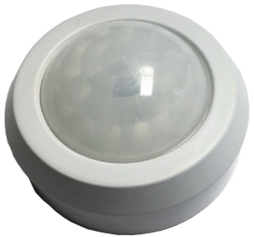
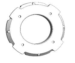
The ClareOne Ceiling Mount 360 PIR sensor is a passive infrared motion detector designed for ceiling mount.
The compact design allows for easy installation while the sensitivity settings provide adaptability for different environments.
The motion detector is designed for a ceiling mount application that provides a 360° detection range.
Notes
- Do not mount the sensor outdoors.
- Avoid areas with pets.
- Do not mount the sensor near ceiling fans or heating ducts.
- Avoid placing the sensor in sight of windows and direct sunlight.
Installation
Before installing the sensor, carefully select the desired location and sensitivity settings.
Location
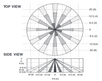
The sensor’s coverage pattern is dependent on mounting height. Areas can be masked off to prevent unwanted detection.
|
Mounting height |
Detection area |
|
8 ft (2.4 m) |
20 ft (6.09 m) |
|
10 ft (3.04 m) |
30 ft (9.14 m) |
|
12 ft (3.65 m) |
45 ft (13.71 m) |
Detector sensitivity can be set to allow for harsher environments with varying temperatures.
 Sensitivity setting
The sensor has 2 sensitivity settings: low and high.
Low (Lo): The recommended setting, allows for some environmental movement.
High (Hi): A quick response, used for quiet areas that do not expect environmental noise.
To select the sensitivity level:
- Gently twist the sensor top and pull the domed top away from the base.
- Place the jumper into the desired sensitivity level (Lo or Hi).
Lo Sensitivity: Jumper placement in the top two pins.
Hi Sensitivity: Jumper placement in the bottom two pins.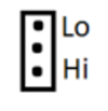
- Replace the sensor top, twisting it firmly into place.
LED
The LED jumper is used to enable/disable a red LED to illuminate when movement is detected. The red LED does not illuminate unless the LED jumper is installed across the pins.
Note: Leaving the LED jumper installed greatly reduces the sensor’s battery life.
Mounting the sensor
After selecting the mounting location and adjusting the sensitivity settings, mount the sensor.
To mount the sensor:
- Attach the tamper spring to the sensor’s plastic foot, A, and attach the foot to the tamper switch, B.
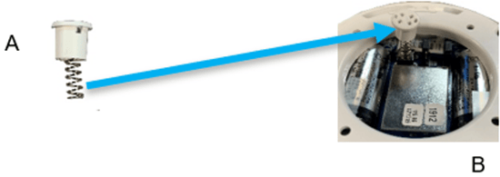
- Remove the housing base from the detector.
- Use the anchors and screws to securely mount the housing base to the ceiling.
- Gently twist the detector on the housing base.
Programming
Add the sensor to the ClareOne panel.
To add the sensor to the ClareOne panel:
- Ensure the sensor is not faulted (no motion currently detected).
- Put the ClareOne panel into sensor paring mode. For detailed programming instructions, refer to the ClareOne Wireless Security and Smart Home Panel User Manual (DOC ID 1871).
- Trip the sensor by causing motion detection.
Testing the sensor
Verify that the sensor is working correctly:
To test the sensor:
- Carefully remove the sensor from the housing base.
- Press the tamper on the motion board to enter Walk Test mode. When in this mode the detector transmits an RF signal to the control panel whenever it detects motion.
- Place the jumper across the LED pins, allowing the LED to light when motion is detected.
- Return the detector to its location, and then walk the coverage area verifying the LED illuminates when movement is detected.
- The Walk Test times out after 1-minute. of no motion detection.
- When finished twist the sensor away from the housing. Remove the LED jumper, and then replace the sensor in its secure housing.
Note: Leaving the LED jumper installed greatly reduces the sensor’s battery life.
Communication delay
The sensor has a 3-minute communication time delay between motion detections. This delay helps conserve battery.
The red LED does not illuminate unless the LED jumper is installed.
Note: Leaving the LED jumper installed greatly reduces the sensor’s battery life.
Replacing the Batteries
Battery life depends on how often the detector transmits signals and the temperature of the installation environment. When the battery voltage gets low, the detector transmits a low battery signal to the panel. The panel then activates trouble beeps to notify the customer that both detector batteries must be replaced.
Replace both batteries immediately using 2 Panasonic CR123A 3V.
Note: If a low battery alarm occurs, replace both batteries within 7 days.
Caution: Batteries may explode if mistreated. Do not recharge, disassemble, or dispose of in fire.
Battery Disposal
The batteries used in this sensor are lithium batteries and are not reusable. Properly dispose of used lithium batteries according to your local hazardous waste disposal laws.
Specifications
|
Compatible panel |
ClareOne (CLR-C1-PNL1) |
|
Power source |
2 CR123A 3V Battery |
|
Transmitter frequency |
433 MHz |
|
Typical battery life |
4 to 6 years |
|
Tamper switch |
Sealed dome contact |
|
Sensitivity |
2-event or 3-event |
|
Dimensions |
2.95 × 1.39 in. (79.93 × 35.30 mm) |
|
Housing |
High impact ABS |
|
Storage temperature |
-30° to 140° F (-34° to 60° C) |
|
Operating environment |
|
Full PDF - ClareOne Ceiling Mount 360 Motion Sensor Installation Sheet (DOC ID 1996)