Last Modified: 01/13/21
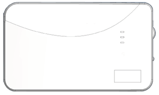
This article will guide you through the process of installing and setting up your W2WL device.
Features
- Selectable wireless sensor compatibility
- Translator or repeater operation
- Rechargeable backup battery
- Cover tamper and wall tamper
- Certified to UL1023, ULC1023, UL1610, and ULCS304
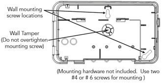
W2WL enclosure interior for mounting
Quick Setup
1. Mount and Wire
- Select a mounting position and location.
- Connect the power supply to the translator.
2. Translator Configuration
- Turn the PANEL SELECT knob to ClareOne.
- Select the brand of sensors that the translator must listen to using the SENSOR SELECT
- Sensor configuration: The translator must learn the sensors that are to be translated or repeated.
- Press the CONFIGURE button to enter configuration mode. The amber LED will illuminate and stay on.
- Tamper or trip all sensors that need to be repeated by the W2WL. The W2WL will beep each time a sensor is enrolled.
Note: Sensors with multiple inputs may need to be tripped separately to enroll each input. - Press the CONFIGURE button to exit configuration mode. The amber LED will darken.
3. Panel Enrollment
(For full sensor enrollment instructions, refer to Advanced Setup, step 3)
- Access the ClareOne panel’s Sensor Settings (Settings > Installer Settings > Sensor Management > Add Sensors), then select “Wireless to Wireless as the device type. For detailed programming instructions, please refer to the ClareOne Wireless Security and Smart Home Panel User Manual (DOC ID 1871).
- Trip the translator tamper to enroll the translator into the panel.
- or -
- Enter ID into panel. The Translator’s ID is printed on the bar code label.
- Access the ClareOne panel’s Sensor Settings, then select the type of sensor to add. Trip one of the repeated or translated sensors to enroll it with the panel.
- Repeat step 2 for each repeated or translated sensor.
4. Finish
- With the translator cover open, perform a panel sensor test.
- Close the cover. Test and verify proper operation of the sensors at the panel.
- Cut the lock wire to lock the translator (for more information on locking, refer to the Advanced Setup section below).
CAUTION: Cutting the lock wire prevents the removal of sensors from the W2WL. - Secure cover with screw.
Panel Diagram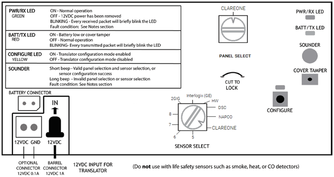
Advanced Setup
1. Mount and Wire
- Select a mounting location and position.
- When configured as a repeater, the W2WL should be placed between the sensors to which it is paired and the ClareOne panel.
- When configured as a translator, the W2WL should be located in a centralized location to the sensors that are paired to it. The W2WL must be at least 5 feet away from the ClareOne panel to allow for proper wireless communication. Do NOT mount the W2WL in a metal can or on a metal surface.
- Verify adequate RF signal strength at the panel before permanently mounting.
- Connect the power supply to the W2WL using the supplied barrel connector.
- Rotate the barrel plug down to the right so the wires exit the enclosure through the strain relief area.
- Ensure the backup battery connector is plugged into the translator.
- Do not connect to a receptacle controlled by a switch.
- In the United States, the transformer must be secured to an outlet.
- In Canada, the transformer must NOT be secured to the outlet.
2. Translator configuration
- Set the PANEL SELECT knob to ClareOne.
- Select the brand of sensors that the translator must listen to using the SENSOR SELECT
- Sensor Configuration: The translator must learn the sensors that are to be translated or repeated.
- Press and release the CONFIGURE button to enter translator configuration mode. The yellow LED will turn on when translator configuration mode is entered.
- Tamper or trip all sensors to be included in the system. The translator beeps for each sensor that is included in the system.
- Press CONFIGURE button to exit translator configuration mode. The yellow LED will turn off when the translator mode is exited.
3. Panel Enrollment:
- Access the ClareOne panel’s Sensor Settings (Settings > Installer Settings > Sensor Management > Add Sensors), then select “Wireless to Wireless” as the device type. For detailed programming instructions, please refer to the ClareOne Wireless Security and Smart Home Panel User Manual (DOC ID 1871).
- Trip the cover tamper to enroll the W2WL into the panel.
-or-
Enter ID into panel. The W2WL’s base ID is printed on the bar code label.
- Access the ClareOne panel’s Sensor Settings, then select the type of sensor to add. Trip one of the repeated or translated sensors to enroll it with the panel.
- Repeat step 3 for each repeated or translated sensor.
4. Finish
- With the translator cover open, perform a panel sensor test.
- When the translator cover is open, the translator will only send sensor transmissions to the panel if the received sensor transmissions have enough signal margin to be reliably received by the translator.
- Closing the translator cover exits the translator sensor test mode. When the translator is not in sensor test mode, all received sensor transmissions are sent to the panel.
- Translator sensor test mode is locked out 24 hours after power up. To re-enable sensor test mode, the translator must be power-cycled by removing both 12VDC input power and backup batter for at least 5 seconds.
- Close the cover. Test and verify proper operation at the panel. Ensure all sensor alarms are reported properly to the central station.
- Translator locking.
CAUTION: Manual W2WL locking cannot be undone.
Locking the translator locks all translator configuration settings and provides takeover protection.
Note: If the lock wire is not cut, the translator automatically locks after 30 days of continuous operation. The effects are the same as manual locking; however, the automatic lock can be reset by power cycling the translator while the cover is open.
CAUTION: Manual W2WL locking cannot be undone.
- Ensure all sensors are functioning as desired.
- Carefully review the effects of manual translator locking before proceeding.
- The translator cannot be factory defaulted once the lock wire is cut.
- Existing sensor configurations cannot be changed. However, new sensors may be configured.
- Panel selection cannot be changed.
- Sensor selection cannot be changed.
- Manual W2WL LOCKING CANNOT BE UNDONE.
- Open the translator cover and cut the lock wire. The green and red LEDs flash and the sounder beeps to confirm.
Note: If the lock wire is not cut, the translator will automatically lock after 30 days of continuous operation. The effects are the same as manual locking; however the automatic lock can be reset by power cycling translator while the cover is open. - With the cover closed, insert the cover securing screw into the screw hole near the cover latch.
Sensor notes
- Do not use with life safety sensors such as smoke, heat, or CO detectors.
- If the translator loses both 12VDC input power and battery up power, sensor configuration data is retained.
- Low battery, tamper, and supervisory signals are reported by the translator on its ID.
- Low battery signals from the translator are suppressed in the first 24-hours after power-up. However, a missing battery condition is reported right away.
- The translator does not support multiple loops on Honeywell® sensors. Only one loop may be used, reed or external.
- When Sensor Select is set to 2GIG®, both Honeywell® and 2GIG® sensors will be translated or repeated.
- Napco® Panic transmitters are not supported.
- All Honeywell® sensors are automatically paired as a door/window sensor if enrolled via FusionPro.
Fault conditions
12VDC input overvoltage fault: Continually flashes and beeps on the green LED and speaker.
12VDC input removed fault: Green LED turns off and the speaker makes a long beep.
Factory default
- To return the translator to a factory default condition, press and hold the configure button. After a couple seconds, the sounder will start beeping rapidly. Continue holding the button until the sounder stops beeping.
- Factory default is not possible if the translator lock wire has been cut.
Specifications
|
Compatible panels |
ClareOne |
|
RF frequency |
433.95MHz |
|
Sensor support |
Up to 128 |
|
Dimensions |
8.5 × 5 × 1.3 in. |
|
Weight with battery |
16 ounces |
|
Tamper activation |
Cover opening, wall removal |
|
Mounting screws |
#4 or #6 |
|
Battery |
|
|
Power supply input |
100-240VAC 50/60Hz 0.5A |
|
Power supply output |
12VDC 1A |
|
Operating environment Temperature Relative humidity |
32 to 120°F (0 to 49°C) 85% noncondensing |
|
Storage temperature |
-4 to 86°F (-20 to 30°C), long term |
|
Certifications ETL Listings: Other |
UL1023, ULC1023, UL1610, ULC S304 FCC, IC |
Key FOB Mapping Table
|
ClareOne |
Honeywell |
2GIG |
Interlogix/GE |
DSC |
NAPCO |
|
Off |
Off |
Unlock |
Unlock |
Off |
Off |
| Away | On | Away | Lock | Home | On |
| Stay | Left | Stay | Lights | Away | Left (A1) |
| Panic | Right | Away+Unlock | Lock+Unlock | Panic | Right (A2) |
| No Action | -- | Star | Star | -- | -- |
Regulatory information
|
Manufacturer |
Clare Controls, Llc. |
|
FCC compliance |
This device complies with part 15 of the FCC Rules. Operation is subject to the following two conditions: (1) This device may not cause harmful interference, and (2) this device must accept any interference received, including interference that may cause undesired operation. FCC ID: U5X-RE524X |
|
Environmental class |
UL: Indoor dry |
|
EU compliance |
|
|
EN 54 |
EN 54-00:0000 |
|
European Union directives |
1999/5/EC (R&TTE directive): Hereby, Clare Controls declares that this device is in compliance with the essential requirements and other relevant provisions of Directive 1999/5/EC. |
 |
2002/96/EC (WEEE directive): Products marked with this symbol cannot be disposed of as unsorted municipal waste in the European Union. For proper recycling, return this product to your local supplier upon the purchase of equivalent new equipment, or dispose of it at designated collection points. For more information see: www.recyclethis.info. |
 |
2006/66/EC (battery directive): This product contains a battery that cannot be disposed of as unsorted municipal waste in the European Union. See the product documentation for specific battery information. The battery is marked with this symbol, which may include lettering to indicate cadmium (Cd), lead (Pb), or mercury (Hg). For proper recycling, return the battery to your supplier or to a designated collection point. For more information see: www.recyclethis.info. |
Notes:
- This product is not for use with life safety sensors (such as smoke, heat, or CO detectors).
- Do not use this product in bank installations.
Full PDF - ClareOne Wireless to Wireless Translator/Repeater Installation Sheet (DOC ID 1990)