Part number: CLR-C1-PIR
Description
The ClareOne PIR Motion Sensor is designed to fit seamlessly in the corner of the room or alongside a wall/door. When the PIR senses motion it transmits an alarm notification to the ClareOne panel.
Important safety instructions
Before you install this sensor, be sure to:
- Read, keep, and follow all instructions.
- Do not install near any heat sources such as radiators, heat registers, stoves, or other apparatus (including amplifiers) that produce heat.
- When there is a low battery, replace with a compatible lithium ion battery.
Installation
Note: We recommend adding the motion sensor to the ClareOne panel before installation. For adding a sensor, see ClareOne User Guide (DOC ID 1871).
The motion sensor can be installed using the provided adhesive or screws.
Note: We recommend using the provided screws for installation. This method is more secure than using adhesive alone.
To install the motion sensor:
- Select the desired position for the sensor.
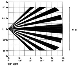
Note: The sensor only detects motion within 3.28 ft. (1 m) below it and installed at 6.88 ft. (2.1 m) having a range of 32.80 ft. (10 m). - Remove the sensor’s battery pull tab.
- Add the sensor to the panel. See “Sensor Management,” ClareOne User Guide (DOC ID 1871).
Note: You must press the button on the side of the sensor to pair the sensor to the panel./MS%20-%20pair%20button-1.png?width=110&name=MS%20-%20pair%20button-1.png)
- Adhere the sensor to the wall using the provided screws or adhesive.
Note: We recommend using the provided screws for installation. This method is more secure than using adhesive alone.Screws
- Locate the bottom of the sensor (the slotted flat end), and then use a screwdriver to remove the casing’s screw.
/MS%20-%20bottom.png?width=150&name=MS%20-%20bottom.png)
- Gently slide a fingernail/fingertip into the slot and push the top casing of the sensor upward.
/MS%20-%20opening%20sensor.png?width=150&name=MS%20-%20opening%20sensor.png)
- (Optional) Mark the screw hole locations, then using a power drill, drill holes and install the 2 provided wall anchors.
- Remove the adhesive film cover, and then place the back plate against the wall, making sure that the orientation is correct for the desired position.
/MS%20-%20peel%20adhesive.png?width=150&name=MS%20-%20peel%20adhesive.png)
- Insert the included mounting screw into the screw breakaway screw hole, using a screwdriver to fully secure the backplate to the wall.
/MS%20-%20screw%20in.png?width=150&name=MS%20-%20screw%20in.png)
- Before finishing installation, set the PINs and jumpers to the desired position. See, Pin function on page 4.
- Once the sensor is configured as desired, press the sensor cover against the base, until there is an audible snap.
/MS%20-%20side%20view%20-%20press%20on.png?width=150&name=MS%20-%20side%20view%20-%20press%20on.png)
- Use the sensor’s casing screw to secure the cover.
Adhesive
- Locate the bottom of the sensor (the slotted flat end), and then use a screwdriver to remove the casing’s screw.
- Gently slide a fingernail/fingertip into the slot and push the top casing of the sensor upward.
- Set the PINs and jumpers to the desired position. See, Pin function.
- Once the sensor is configured as desired, press the sensor cover against the base, until there is an audible snap.
/MS%20-%20press%20on%20-%20no%20wall.png?width=180&name=MS%20-%20press%20on%20-%20no%20wall.png)
- Use the sensor’s casing screw to secure the cover.
- Peel the film cover off of the adhesive, and then firmly press the sensor back plate against the wall.
Note: Once placed, the sensor cannot be moved without damaging the adhesive.
- Locate the bottom of the sensor (the slotted flat end), and then use a screwdriver to remove the casing’s screw.
- Once added, test the sensor. Look at the ClareOne panel, and then open the door/window. Notice that the added sensor displays faulted.
Note: Testing all sensors with the alarm monitoring station is strongly advised.
Figure 1: Sensor range and detection
/Sensor%20-height%20and%20distance.png?width=300&name=Sensor%20-height%20and%20distance.png)
Motion detector Walk Test
The motion detector Walk Test allows the installer the ability to check the detection range.
To perform the motion detector Walk Test:
- Verify that the sensor is paired to the ClareOne panel.
- Remove the battery.
See “To replace the battery." - Press and hold the tamper switch while replacing the battery.
- Walk Test mode is now active.
- Walk around the desired detection area and verify that sensor can detect motion at the desired range/area.
Notes
- The LED flashes when the sensor detects motion.
- The LED can be triggered every 10 seconds.
- The sensor remains in Walk Test mode until the battery is removed and replaced.
- Remove and replace the battery.
The sensor is now in normal mode.
Battery replacement
The CLR-C1-PIR requires a CR123A battery. Once the battery is low, the panel displays a low battery icon next to the sensor in the devices list. The battery must be replaced within 7 days of the first low battery notification. If the battery is not replaced within 7 days, the sensor may not function properly.
WARNING: If an incompatible replacement battery is used, or the battery is installed incorrectly explosion or damages may occur.
AVERTISSEMENT: Si une batterie de remplacement incompatible est utilisée ou si la batterie est installée de manière incorrecte, une explosion ou des dommages peuvent survenir.
To replace the battery:
Note: Verify that the panel is not armed before changing the battery.
- Locate the bottom of the sensor (the slotted flat end), and then use a screwdriver to remove the casing’s screw.
- Gently slide a fingernail/fingertip into the slot and push the top casing of the sensor outward, away from the wall.
/MS%20-%20wall%20mounted%20-%20remove%20cover.png?width=150&name=MS%20-%20wall%20mounted%20-%20remove%20cover.png)
- Use a fingernail/fingertip to push the battery out of the casing, noting the polarity of the battery.
/MS%20-%20battery%20removal.png?width=150&name=MS%20-%20battery%20removal.png)
- Insert a new CR123A battery into the battery casing, making sure that the polarity is correct.
/MS%20-%20new%20battery%20in.png?width=150&name=MS%20-%20new%20battery%20in.png)
- Press the sensor cover back onto its back plate. There will be an audible snap.
/MS%20-%20wall%20mount%20-%20replace%20cover.png?width=150&name=MS%20-%20wall%20mount%20-%20replace%20cover.png)
- Use the sensor’s casing screw to secure the cover
- Test the sensor.
Pin function
The PIR Motion Sensor has 2 sets of adjustable pins. The pins adjust the Pet Immunity setting and the Sensitivity level. Each set of pins has 2 settings that can be selected.
Figure 2: Sensor pins and tamper switch
/MS%20-%20callouts.png?width=260&name=MS%20-%20callouts.png)
|
(1) Pet immunity pins |
(3) Sensitivity pins |
Table 1: Pin configuration
|
Configuration |
Pet Immunity |
Sensitivity |
|
Top and middle pin
|
Up to 33lb dog |
Low – max of |
|
Middle and bottom pin
|
Up to 55lb dog |
High – max of |
/MS%20-%20top%20both.png?width=180&name=MS%20-%20top%20both.png)
/MS%20-%20bottom%20both.png?width=180&name=MS%20-%20bottom%20both.png)
Pet Immunity
The pet immunity pins allow the user to select the desired immunity level. Place the selector over the desired pin configuration.
To change the pet immunity level:
- Remove the back plate from the motion sensor.
- Turn the sensor over so the battery faces up.
- Locate the pet immunity pins on the left side.
- Gently pinch the jumper and pull upward and away from the sensor.
All 3 pins are visible./MS%20-%20side%20view%20of%20pins.png?width=180&name=MS%20-%20side%20view%20of%20pins.png)
- Gently press the jumper on the desired pin set.
See Table 1: Pin configuration./MS%20-%20bottom%20pet%20pins.png?width=180&name=MS%20-%20bottom%20pet%20pins.png)
- Replace the sensor plate, and then continue to installation.
- Or -
Adjust the sensitivity level, and then continue to installation.
Sensitivity
The sensitivity pins allow the user to select the desired sensitivity level. Place the selector over the desired pin configuration.
To change the sensitivity level:
- Remove the back plate from the motion sensor.
- Turn the sensor over so the battery faces up.
- Locate the sensitivity pins on the right side.
- Gently pinch the jumper and pull upward and away from the sensor.
All 3 pins are visible. - Gently press the jumper on the desired pin set.
- Replace the sensor plate, and then continue to installation.
- Or -
Adjust the pet immunity level, and then continue to installation.
Specifications
|
Compatible panel |
ClareOne |
|
Transmitter frequency |
433MHz |
|
Encrypted |
Yes |
|
Pet immunity |
Up to 55lb dog |
|
Detection length |
Default: 32.80 ft. (10 m) |
|
Detection angle |
90 degrees |
|
Transmitted indications |
Tamper and low battery |
|
Supervisory keep-alive |
60 to 70 minutes |
|
PIR function |
Sensitivity (2 stops) |
|
Button |
Pairing |
|
Battery type |
CR123A (1300mAh) |
|
Battery life |
4 to 5 years |
|
Operating environment Temperature |
|
|
Sensor dimensions |
2.16 × 2.99 × 1.65 in. |
|
Water resistant |
No |
|
Certifications |
FCC: 15.109 Class B 15.231, Industry Canada: ICES-003, RSS-210, ETL listed to: UL639, CAN/ULC-C306 |
Full PDF - ClareOne PIR Motion Sensor Installation Sheet (DOC ID 1898)